Home » Posts tagged 'Raspberry Pi'
Tag Archives: Raspberry Pi
A Better Mobile Display for the Raspberry Pi

iSSH Terminal Session
As I described in an earlier post, I run my Raspberry Pi (RPi) as a headless system, using Cygwin/X‘s xterm for command line interaction with the RPi, with my PC being my X server to support any X Window applications. I can move files between the PC and the RPi via my pseudo-Dropbox. I really recommend this configuration and its working perfectly for me.
This configuration gives me a great deal of utility but no mobility …. I’m still tied to my desktop PC. Maybe I should consider replacing the desktop PC with a laptop but I don’t want to spend the money. I have seen some small, inexpensive keyboards and displays that could be connected directly to the RPi, and you could cobble together a mobile unit, or the more elegant Kindle version, but this still doesn’t give me the mobility look & feel I would like.
iPad to the rescue (assuming you have one ….)! I found a great app call iSSH by Zingersoft. Its claims that it is a “comprehensive VT100, VT102, VT220, ANSI, xterm, and xterm-color terminal emulator over SSH and telnet, integrated with a tunneled X server, RDP and VNC client. ” I installed it, configured it quickly, and got a terminal connection to the RPi without reading the documentation …. Impressive since successfully configuring ssh, Xserver, etc. can be challenging sometimes. (Note: The easy of this was largely due to setting up RPi environment properly in the first place. See the earlier post). To top it off, iSSH has a slick look & feel.
Configuring iSSH

iSSH X Server Session
Zingersoft’s documentation on configuring iSSH is easy to follow and requires just a few steps. I had no problem getting an terminal session working to the RPi but I did have problems with graphics programs (i.e. X Window client programs). It appears that iSSH’s terminal isn’t really xterm but a terminal emulation (secured via ssh). The iSSH terminal doesn’t use the X server. In fact, while in the terminal session, to see the X server display (i.e. to see graphics applications rendered via the RPi X client) you must hit the button at the top right of the iPad display.
Frankly, the fact that the X application didn’t work the first time wasn’t a big surprise to me. I have been struggling with getting my X Window configuration set up to work reliably for some time. What I was observing was that X would work fine for sometime but at some point I would get the error message “couldn’t connect to display”.
This error is very common and nearly every X user has seen some version of this before. I assume that the right way to solve this was to gain a deeper understanding of X Windows and discover its root cause . I did gain a deeper understanding of X Windows, but a solution to my problem never jumped out from the “official” materials I read. I found the solution when I happened upon the blog “X11 Display Forwarding Fails After Some Time“.
The root cause of my error message is the time out of the X Forwarding. I have been using the -X option when using ssh. This is the more secure option for X Forwarding, but comes at a price, as shown below.
- Using
ssh -X, X forwarding is enabled in “Untrusted” mode, making use of various X security extensions, including a time-limited Xauth cookie. - Use
ssh -Yto enable “Trusted” mode for X, which will enable complete access to your X server. There is no timeout for this option.
So my Display problem isn’t really an error, per say, but ssh timing out on me. To fix this, I added the entry ForwardX11Timeout 596h into my ~/.ssh/config file on my PC. With this problem solved, I continued my journey into X.
My Journey to a Better Understanding of X
Using X Windows for the first time can be somewhat of a shock to someone familiar with other graphical environments, such as Microsoft Windows or Mac OS. X was designed from the beginning to be network-centric, and uses a “client-server” model. In the X model, the “X server” runs on the computer that has the keyboard, monitor, and mouse attached. The server’s responsibility includes tasks such as managing the display, handling input from the keyboard and mouse, and other input or output devices (i.e., a “tablet” can be used as an input device, and a video projector can be an output device, etc.). Each X application (such as xterm) is a “client”. A client sends messages to the server requesting things like “Please draw a window at these coordinates”, and the server sends back messages such as “The user just clicked on the OK button”. These standardized set of messages make up the X Protocol.
The X server and the X clients commonly run on the same computer. However, it is perfectly possible to run the X server on a less powerful computer (e.g. in my case a PC or iPad), and run X applications (the clients) on a powerful machine that serves multiple X servers (or it can be a simple RPi, as in my case). In this scenario the communication between the X client and server takes place over the network (WiFi for my iPad), via the X Protocol. There is nothing in the protocol that forces the client and server machines to be running the same operating system, or even to be running on the same type of computer.
The Display
It is important to remember that the X server is the is the software program which manages the monitor, keyboard, and pointing device. In the X window system, these three devices are collectively referred to as the “display”. Therefore, the X server serves displaying capabilities, via the display, to other programs, called X clients, that connect to the X server. All these connections are established via the X protocol.
The relationship between the X server and the display are tight, in that the X server is engineered to support a specific display (or set of displays). As a user of X, you don’t have any control over this relationship, only the software developer who created the server can modify this relationship (generally speaking). On the other hand, as a user you have free hand in configuring the X protocol connection between the X server and the X clients.
How do you establish a X Protocol connection between any given server and a client? This is done via the environment variable “DISPLAY”. A Linux environment variable DISPLAY tells all its X clients what display they should use for their windows. Its value is set by default in ordinary circumstances, when you start an X server and run jobs locally. Alternatively, you can specify the display yourself. One reason to do this is when you want log into another system, and run a X client there, and but have the window displayed at your local terminal. That is, the DISPLAY environment variable must point to your local terminal.
So the environment variable “DISPLAY” stores the address for X clients to connect to. These addresses are in the form: hostname:displaynumber.screennumber where
hostnameis the name of the computer where the X server runs. An omittedhostnamemeans the localhost.displaynumberis a sequence number (usually 0). It can be varied if there are multiple displays connected to one computer.screennumberis the screen number. A display can actually have multiple screens. Usually there’s only one screen though where 0 is the default.
Setting the DISPLAY variable depends of your shell, but for the Bourne, Bash or Korn shell, you could do the following to connect with the systems local display:
export DISPLAY=localhost:0.0
The remote server knows where it have to redirect the X network traffic via the definition of the DISPLAY environment variable which generally points to an X Display server located on your local computer.
X Security
So you see, as the user, you have full control over where you wish to display the X client window. So what prevents you from doing something malicious, like popping up window on someone else terminal or read their key strokes? After all, all you really need is their host name. X servers have three ways of authenticating connections to it: the host list mechanism (xhost) and the magic cookie mechanism (xauth). Then there is ssh, that can forward X connections, providing a protected connection between client and server over a network using a secure tunnelling protocol.
The xhost Command
The xhost program is used to add and delete host (computer) names or user names to the list of machines and users that are allowed to make connections to the X server. This provides a rudimentary form of privacy control and security. A typical use is as follows: Let’s call the computer you are sitting at the “local host” and the computer you want to connect to the “remote host”. You first use xhost to specify which computer you want to give permission to connect to the X server of the local host. Then you connect to the remote host using telnet. Next you set the DISPLAY variable on the remote host. You want to set this DISPLAY variable to the local host. Now when you start up a program on the remote host, its GUI will show up on the local host (not on the remote host).
For example, assume the IP address of the local host is 128.100.2.16 and the IP address of the remote host is 17.200.10.5.
On the local host, type the following at the command line:
xhost + 17.200.10.5
Log on to the remote host
telnet 17.200.10.5
On the remote host (through the telnet connection), instruct the remote host to display windows on the local host by typing:
export DISPLAY=128.100.2.16:0.0
Now when you type xterm on the remote host, you should see an xterm window on the local host. You should remove the remote host from your access control list as follows.
xhost - 17.200.10.5
Some additional xhost commands:
xhost List all the hosts that have access to the X server
xhost + hostname Adds hostname to X server access control list.
xhost - hostname Removes hostname from X server access control list.
xhost + Turns off access control (all remote hosts will have access to X server … generally a bad thing to do)
xhost - Turns access control back on (all remote hosts blocked access to X server)
Xhost is a very insecure mechanism. It does not distinguish between different users on the remote host. Also, hostnames (addresses actually) can be spoofed. This is bad if you’re on an untrusted network.
The xauth Command
Xauth allows access to anyone who knows the right secret. Such a secret is called an authorization record, or a magic cookie. This authorization scheme is formally called MIT-MAGIC-COOKIE-1. The cookies for different displays are stored together in the file .Xauthority in the user’s home directory (you can specify a different cookie file with the XAUTHORITY environment variable). The xauth application is a utility for accessing the .Xauthority file.
On starting a session, the X server reads a cookie from the.Xauthority file. After that, the server only allows connections from clients that know the same cookie (Note: When the cookie in .Xauthority changes, the server will not pick up the change.). If you want to use xauth, you must start the X server with the -auth authfile argument. You can generate a magic cookie for the .Xauthority file using the utility mcookie (typical usage: xauth add :0 . `mcookie`).
Now that you have started your X session on the server and have your cookie in .Xauthority, you will have to transfer the cookie to the client host. There are a few ways to do this. The most basic way is to transfer the cookie manually by listing the magic cookie for your display with xauth list and injecting it into the remote hosts .Xauthority via the xauth utility.
Xauth has a clear security advantage over xhost. You can limit access to specific users on specific computers and it does not suffer from spoofed addresses as xhost does.
X Over SSH
Even with the xhost and xauth methods, the the X protocol is transmitted over the network with no encryption. If you’re worried someone might snoop on your connections (and you should worry), use ssh. SSH, or the Secure Shell, allows secure (encrypted and authenticated) connections between any two devices running SSH. These connections may include terminal sessions, file transfers, TCP port forwarding, or X Window System forwarding. SSH supports a wide variety of encryption algorithms. It supports various MAC algorithms, and it can use public-key cryptography for authentication or the traditional username/password.
SSH can do something called “X Forwarding” makes the communication secure by “tunneling” the X protocol over the SSH secure link. Forwarding is a type of interaction with another network application, through a inter-mediator, in this case SSH. SSH intercepts a service request from some other program on one side of an SSH connection, sends it across the encrypted connection, and delivers it to the intended recipient on the other side. This process is mostly transparent to both sides of the connection: each believes it is talking directly to its partner and has no knowledge that forwarding is taking place. This is called tunneling since X protocol is encapsulated within the a SSH protocol.
When setting up an SSH tunnel for X11, the Xauth key will automatically be copied to the remote system(in a munged form to reduce the risk of forgery) and the DISPLAY variable will be set.
To turn on X forwarding over ssh, use the command line switch -X or write the following in your local ssh configuration file:
Host remote.host.name

ForwardX11 yes
The current version of SSH supports the X11 SECURITY extension, which provides two classes of clients: trusted clients, which can do anything with the display, and untrusted clients, which cannot inject synthetic events (mouse movement, keypresses) or read data from other windows (e.g., take screenshots). It should be possible to run almost all clients as untrusted, leaving the trusted category for screencapture and screencast programs, macro recorders, and other specialized utilities.
If you use ssh -X remotemachine the remote machine is treated as an untrusted client and ssh -Y remotemachine the remote machine is treated as trusted client. ‘-X’ is supposedly the safe alternative to ‘-Y’. However, as a Cygwin/X maintainer says “this is widely considered to be not useful, because the Security extension uses an arbitrary and limited access control policy, which results in a lot of applications not working correctly and what is really a false sense of security”.
You can configuring SSH via the following files:
- per-user configuration is in
~/.ssh/config - system-wide client configuration is in
/etc/ssh/ssh_config - system-wide daemon configuration is in
/etc/ssh/sshd_config
The ssh server (sshd) at the remote end automatically sets DISPLAY to point to its end of the X forwarding tunnel. The remote tunnel end gets its own cookie; the remote ssh server generates it for you and puts it in~/.Xauthority there. So, X authorization with ssh is fully automatic.
X over SSH solves some of the problems inherent to classic X networking. For example, SSH can tunnel X traffic through firewalls and NAT, and the X configuration for the session is taken care of automatically. It will also handle compression for low-bandwidth links. Also, if you’re using X11 forwarding, you may want to consider setting ForwardX11Trusted no to guard against malicious clients.
The Window Manager
The X design philosophy is much like the Linux/UNIX design philosophy, “tools, not policy”. This philosophy extends to X not dictating what windows should look like on screen, how to move them around with the mouse, what keystrokes should be used to move between windows, what the title bars on each window should look like, etc. Instead, X delegates this responsibility to an application called a “Window Manager”.
There are many window managers available for X and each provides a different look and feel. Some of them support highly configurable virtual desktops like, KDE and GNOME, some of them are lightweight desktop like LXDE which comes with the RPi, or you can operate bare bones (like I am on my PC while using the RPi) and let MS Windows be your Window Manager via Cygwin/X. The iPad’s iSSH can run without a Window Manager. In effect, X server uses the display as it sees fit and your unable to control where things loaded. iSSH does have a Window Manage your can use as an option called dwm. Its a tiling window manager, which is a reasonable way to go given that your pointing device is your finger on the iPad.
X Display Manager
The X Display Manager (XDM) is an optional part of the X Window System that is used for login session management. XDM provides a graphical interface for choosing which display server to connect to, and entering authorization information such as a login & password. Like the Linux getty utility, it performs system logins to the display being connected to and then runs a session manager on behalf of the user (usually an X window manager). XDM then waits for this program to exit, signaling that the user is done and should be logged out of the display. At this point, XDM can display the login and display chooser screens for the next user to login.
In the small world of my RPi’s, a PC, and an iPad, I have no need for an XDM and don’t use one.
Enough of the X Journey … Now in Conclusion
So what does the iSSH give me? I can now sit on the couch, watch TV, and simultaneously login into the RPi with full X Windows support. Some would call this Nirvana but I call it just VERY NICE. The iPad/iSSH combination isn’t the perfect user experience but Zingersoft did a good job.
By the way …. the above iPad screen shot of the X Server display with a globe was rendered using the following code:
#!/usr/bin/env python

"""
    Source: http://www.scipy.org/Cookbook/Matplotlib/Maps
"""

from mpl_toolkits.basemap import Basemap
import matplotlib.pyplot as plt
import numpy as np

Use_NASA_blue_marble_image = False

# set up orthographic map projection with
# perspective of satellite looking down at 50N, 100W.
# use low resolution coastlines.
# don't plot features that are smaller than 1000 square km.
map = Basemap(projection='ortho', lat_0=50, lon_0=-100, resolution='l', area_thresh=1000.)

# draw coastlines, country boundaries, fill continents.
if Use_NASA_blue_marble_image:
    map.bluemarble()
else:
    map.drawcoastlines()
    map.drawcountries()
    map.fillcontinents(color='coral')

# draw the edge of the map projection region (the projection limb)
map.drawmapboundary()

# draw lat/lon grid lines every 30 degrees.
map.drawmeridians(np.arange(0, 360, 30))
map.drawparallels(np.arange(-90, 90, 30))

# lat/lon coordinates of five cities.
lats = [40.02, 32.73, 38.55, 48.25, 17.29]
lons = [-105.16, -117.16, -77.00, -114.21, -88.10]
cities = ['Boulder, CO', 'San Diego, CA', 'Washington, DC', 'Whitefish, MT', 'Belize City, Belize']

# compute the native map projection coordinates for cities.
x, y = map(lons, lats)

# plot filled circles at the locations of the cities.
map.plot(x, y, 'bo')

# plot the names of those five cities.
for name, xpt, ypt in zip(cities, x, y):
        plt.text(xpt + 50000, ypt + 50000, name)

# make up some data on a regular lat/lon grid.
nlats = 73
nlons = 145
delta = 2. * np.pi / (nlons - 1)
lats = (0.5 * np.pi - delta * np.indices((nlats, nlons))[0, :, :])
lons = (delta * np.indices((nlats, nlons))[1, :, :])
wave = 0.75 * (np.sin(2. * lats) ** 8 * np.cos(4. * lons))
mean = 0.5 * np.cos(2. * lats) * ((np.sin(2. * lats)) ** 2 + 2.)

# compute native map projection coordinates of lat/lon grid.
x, y = map(lons * 180. / np.pi, lats * 180. / np.pi)

# contour data over the map.
CS = map.contour(x, y, wave + mean, 15, linewidths=1.5)

plt.show()
Configuration Utilities for XBee Radios
 My ultimate aim is to wirelessly network several Arduino based platforms with a centralized Raspberry Pi controller. There is much for me to learn to get this operational, not the least of which is the radio device I plan to use, the Xbee. To get up to speed on the Xbee, I found the tutorials at Adafruit, Sparkfun, and Parallax helpful. More detailed references are listed at the end of this post, but the very first challenge is to configure the XBee radios for operation. This post provides insight on how this can be done, and my main mission, create a few simple utilities that make that job easy.
Xbee Radios
I purchased two XBee Series 1 Module (Freescale 802.15.4 firmware) from Adafruit. These are manufactured by Digi and are low-power module with wire antenna (XB24-AWI-001). They have a 250 kbps RF data rates and operate at 2.4 GHz. These radios use the IEEE 802.15.4 networking protocol and can perform point-to-multi-point or peer-to-peer networking , but as configured here, they do not mesh. The Digi models that handle meshing are Digimesh, ZNet2.5 and Zigbee (ZB). Digimesh is a version of firmware that runs on Series 1 hardware. So, if you choose to, you can upgrade these modules to Digimesh firmware to get meshing.
Xbee Adapter Board
Along with the XBee radios, I purchased adapter boards designed to make it easier to work with the radios. The adopter provides on-board 3.3V regulator power from a 5 volt source, voltage level shifting circuitry so you can connect 5V circuitry to the XBee, commonly used pins are brought out along the edge (making it easy to breadboard), and engineered to be interface via FTDI cable to a computer via USB. The image and the text below describe the pin-out for the Adafruit XBee Adapter:

Adafruit Xbee Adapter Pinout
- 3V pin – This is either an input power pin (if 5V is not provided) or an output from the 250mA regulator if 5V is provided
- DTR – “Data terminal ready” is a flow control pin used to tell the XBee that the microcontroller or computer host is ready to communicate.
- RST – “Reset” pin can be used to reset the XBee. By default it is pulled high by the 10K resistor under the module. To reset, pull this pin low.’
- Ground – common ground for power and signal
- CTS – “Clear to Send” this is a flow control pin that can be used to determine if there is data in the XBee input buffer ready to be read
- 5V – This is the power input pin into the 3.3V regulator. Provide up to 6V that will be linearly converted into 3.3V
- RX – “Receive Data” is the XBee’s serial recieve pin. Serial data is sent on this pin into the XBee to be transmitted wirelessly
- TX – “Transmit Data” is the XBee’s serial transmit pin. Serial data is sent on this pin out of the XBee, after it has been transmitted wirelessly from another module
- RTS – “Ready to Send” is a flow control pin that can be used to tell the XBee to signal that the computer or microcontroller needs a break from reading serial data.
- see pin #1
The DTR, RTS, RST and RX pins (going into the XBee) pass through a level converter chip that brings the levels to 3.3V. Adafruit claims you can use pretty much anywhere between 2.7 to 5.5V data to communicate with the XBee. The breakout pins on the bottom of the board are not level shifted and you should try to keep data going directly into the XBee pin under 3.3V

Xbee radio installed in a XBee Adapter with the USB FTDI TTL-232 Cable attached
XBee Initial Configuration and Testing
You need a way to communicate withe the Xbee, via it adapter, to set it up. This can be done via Adafruit’s USB FTDI TTL-232 Cable, and the Digi X-CTU serial terminal program. By the way, the X-CTU user guide describes the many more things it can do beyond the configuration shown here.
- Plug in the USB FTDI TTL-232 Cable into a PC USB port. If drivers are not installed automatically (it didn’t for me), follow the steps at the FTDI site.
- Download the X-CTU, double click on the executable file, and follow the instructions to install the program.
- Now connect the USB FTDI TTL-232 Cable to the Xbee Adapter as shown in the picture to the right and insert the USB end of the cable to you PC. Start the X-CTU.
- To connect, configure and upgrading the Xbee, follow the Adafruit instructions for the Xbee Adapter board. Note that if you follow the instructions (I didn’t – I kept it at 9600 baud), the modem’s serial interface is now set to 19,200 baud, not the default 9600 used by X-CTU. Remember this next time you use X-CTU with this Xbee.
- If your instructed by X-CTU to reset the Xbee, you can do this by shorting the reset pin, RST pin, to ground.
The configuration can be touchy, it can go badly, or not at all. In my case, I seem to have one Xbee Adapter that can reliably perform a firmware upgrade but the other one took some time due to a lose fitting between the Adaptor and Xbee. If you run into configuration problems, check out these sites: Using XCTU to Invoke the Bootloader, The Unofficial XBee FAQ, How to recover from a failed firmware upgrade.
Quickly Getting the Xbee’s Communicating
The next step for me was just do a basic test of getting two XBee device communicating with each other. This is just a sanity test to see evidence of communication between the devices. Basically, I just followed the instructions provided by Adafruit.

- Using the X-CTU, set the PAN ID to the same value on the two Xbee’s.
- Select an Ardunio that has been programmed to send repeated brief messages to its serial port. I used the standard LED Blinking sketch but put in some write statements in the loop.
- Using an Arduino and breadboard, connect +5V and ground to provide power. Make sure the XBee’s LED is blinking.
- Connect the RX line (input) of the XBee to the TX line (output) of the Arduino. Connect the RX line (input) of the Arduino to the TX line (output) of the Xbee. Plug the Arduino into your PC’s serial port.
- Now take the second Xbee and connect the USB FTDI TTL-232 Cable to the Xbee and the PC. The cable is doing nothing but appling power to the Xbee.
- Now you should see the receive LED periodically light on the USB FTDI TTL-232 Cable tethered Xbee.
- You now got proof that the two Xbee’s are communicating. The Arduino connected Xbee is sending data to its serial port and the USB FTDI TTL-232 Cable tethered Xbee is receiving it.
Above you’ll find a picture of the configuration, and below is the Arduino sketch I used.
/*
 *  Xbee Test via Blink LED
 *
 *Turns on an LED on for one second, then off for one second, repeatedly.
 *Also increase brigthness of analog LED.
 *
 *The circuit:
 * LED1 connected from digital pin 13 to ground.
 * LED2 connected from analog pin 9 to ground.
 * Note: On most Arduino boards, there is already an LED on the board
 * connected to pin 13, so you don't need any extra components for this example.

 *Created 1 June 2005
 *By David Cuartielles
 *http://arduino.cc/en/Tutorial/Blink
 *based on an orginal by H. Barragan for the Wiring i/o board
 *Modified by Jeff Irland in December 2012
 */

int ledPin1 =  13;    // LED connected to digital pin 13
int ledPin2 =  9;     // LED connected to analog pin 9
int brightness = 0;

// The setup() method runs once, when the sketch starts
void setup()   {
    Serial.begin(9600);
    pinMode(ledPin1, OUTPUT);     // initialize the digital pin as an output
    Serial.println("Arduino done with setup()");
}

// the loop() method runs over and over again,
// as long as the Arduino has power
void loop()
{
    digitalWrite(ledPin1, HIGH);   // set the LED on
    Serial.println("LED set HIGH.");
    delay(1000);                   // wait for a second

    digitalWrite(ledPin1, LOW);    // set the LED off
    Serial.println("LED set LOW.");
    delay(1000);                   // wait for a second

    brightness = brightness + 5;
    analogWrite(ledPin2, brightness);
    Serial.println("LED brightness increased.");
}
Installing XBee Python Tools for the RPi
While the MS Windows based Digi X-CTU tool is just fine, I want to use the RPi’s and Python to access the XBee serial communication API, and its advanced features, for one or more XBee devices. I prefer simple utilities, that can be scripted within the Linux shell. Call me a Linux snob if you wish, but I don’t care for MS Windows!
In my post “Selecting XBee Radios and Supporting Software Tools“, I referenced a Python package that could be used to create my utilitiesd, call python-xbee, and I will be using it here. It claims to provides a semi-complete implementation of the XBee binary API protocol and allows a developer to send and receive the information they desire without dealing with the raw communication details. It also claims the library is compatible with both XBee 802.15.4 (Series 1) and XBee ZigBee (Series 2) modules, normal and PRO.
First, we need to load some additional required Python Packages, that being pySerial and Nose. pySerial extends python’s capabilities to include interacting with a serial port and Nose is a package providing a very easy way to build tests, based on the Python class unittest. (Don’t let this all scare you away, these are necessary but your not going to use them directly). To load these package:
sudo pip install pySerial

sudo pip install nose
Download the python-xbee tools from Google Code or Python Org and place them into the RPi’s $HOME/src. The README file provides installation instructions. It states that the following command automatically test and install the package for you:
sudo python setup.py install
There is a simple to use RPi platform tool that I have modified for my needs, that is a XBee serial command shell for interacting with XBee radios. It performs the core functions of the official configuration tool, X-CTU, which only runs on Windows. (There happens to be a cross-platform version of X-CTU called moltosenso Network Manager but I don’t need all this horse power.) I’ll use this X-CTU-alternative to configure the individual XBee radios. With the X-CTU, you can update firmware, etc. but most of the time you need the program to do simple configuration tasks. You could use Linux’s minicom, but I prefer a simpler tool which can be scripted so I can configure several XBee radios identically. I found much of what I wanted in an existing Python XBee tools for configuration. I made some modification/improvements, I call it the XBeeTerm, and its listed below:
#!/usr/bin/env python """XBeeTerm.py is a XBee serial command shell for interacting with XBee radios This command interpretors establishes communications with XBee radios so that AT Commands can be sent to the XBee. The interpretors output is color coded to help distinguish user input, from XBee radio output, and from interpretors output. This command-line interpretor uses Python modual Cmd, and therefore, inherit bash-like history-list editing (e.g. Control-P or up-arrow scrolls back to the last command, Control-N or down-arrow forward to the next one, Control-F or right-arrow moves the cursor to the right non-destructively, Control-B or left-arrow moves the cursor to the left non-destructively, etc.). XBeeTerm is not a replacement for the Digi X-CTU program but a utility program for the Linux envirnment. You can pipe scripts of XBee configration commands, making it easy to multiple radios. Also, XBeeTerm wait for the arrival of a XBee data packet, print the XBee frame, and wait for the next packet, much like a packet sniffer. XBeeTerm Commands: baudrate <rate> set the baud rate at which you will communicate with the XBee radio serial <device> set the serial device that the XBee radio is attached watch wait for the arrival of a XBee data packet, print it, wait for the next shell or ! pause the interpreter and invoke command in Linux shell exit or EOF exit the XBeeTerm help or ? prints out short discription of the commands (similar to the above) Just like the Digi X-CTU program, the syntax for the AT commands are: AT+ASCII_Command+Space+Optional_Parameter+Carriage_Return Example: ATDL 1F<CR> Example Session: baudrate 9600 # (XBeeTerm command) set the baudrate used to comm. with the XBee serial /dev/ttyUSB0 # (XBeeTerm command) serial device which has the XBee radio +++ # (XBee command) enter AT command mode on the XBee ATRE # (XBee command) restore XBee to factory settings ATAP 2 # (XBee command) enable API mode with escaped control characters ATCE 0 # (XBee command) make this XBee radio an end device ATMY AAA1 # (XBee command) set the address of this radio to eight byte hex ATID B000 # (XBee command) Set the PAN ID to eight byte hex ATCH 0E # (XBee command) set the Channel ID to a four byte hex ATPL 0 # (XBee command) power level at which the RF module transmits ATWR # (XBee command) write all the changes to the XBee non-volatile memory ATFR # (XBee command) reboot XBee radio exit # (XBeeTerm command) exit python shell Referance Materials: XBee 802.15.4 (Series 1) Module Product Manual (section 3: RF Module Configuration) ftp://ftp1.digi.com/support/documentation/90000982_A.pdf python-xbee Documentation: Release 2.0.0, Paul Malmsten, December 29, 2010 cmd - Support for line-oriented command interpreters http://docs.python.org/2/library/cmd.html cmd - Create line-oriented command processors http://bip.weizmann.ac.il/course/python/PyMOTW/PyMOTW/docs/cmd/index.html Easy command-line applications with cmd and cmd2 http://pyvideo.org/video/306/pycon-2010--easy-command-line-applications-with-c Orginally Created By: Amit Snyderman (amit@amitsnyderman.com), on/about August 2012, and taken from https://github.com/sensestage/xbee-tools Modified By: Jeff Irland (jeff.irland@gmail.com) in January 2013 """ # imported modules import os # portable way of using operating system dependent functionality import sys # provides access to some variables used or maintained by the interpreter import time # provides various time-related functions import cmd # provides a simple framework for writing line-oriented command interpreters import serial # encapsulates the access for the serial port import argparse # provides easy to write and user-friendly command-line interfaces from xbee import XBee # implementation of the XBee serial communication API from pretty import switchColor # colored text in Python using ANSI Escape Sequences # authorship information __author__ = "Jeff Irland" __copyright__ = "Copyright 2013" __credits__ = "Amit Snyderman, Marije Baalman, Paul Malmsten" __license__ = "GNU General Public License" __version__ = "0.1" __maintainer__ = "Jeff Irland" __email__ = "jeff.irland@gmail.com" __status__ = "Development" __python__ = "Version 2.7.3" # text colors to be used during terminal sessions CMD_INPUT_TEXT = 'normal' CMD_OUTPUT_TEXT = 'bright yellow' XBEE_OUTPUT_TEXT = 'bright red' SHELL_OUTPUT_TEXT = 'bright cyan' WATCH_OUTPUT_TEXT = 'bright green' class ArgsParser(): """Within this object class you should load all the command-line switches, parameters, and arguments to operate this utility""" def __init__(self): self.parser = argparse.ArgumentParser(description="This command interpretors establishes communications with XBee radios so that AT Commands can be sent to the XBee. It can be used to configure or query the XBee radio", epilog="This utility is primarily intended to change the AT Command parameter values, but could be used to query for the parameter values.") self.optSwitches() self.reqSwitches() self.optParameters() self.reqParameters() self.optArguments() self.reqArguments() def optSwitches(self): """optonal switches for the command-line""" self.parser.add_argument("--version", action="version", version=__version__, help="print version number on stdout and exit") self.parser.add_argument("-v", "--verbose", action="count", help="produce verbose output for debugging") def reqSwitches(self): """required switches for the command-line""" pass def optParameters(self): """optonal parameters for the command-line""" pass def reqParameters(self): """required parameters for the command-line""" pass def optArguments(self): """optonal arguments for the command-line""" self.parser.add_argument(nargs="*", action="store", dest="inputs", default=None, help="XBeeTerm script file with AT Commands to be executed") def reqArguments(self): """required arguments for the command-line""" pass def args(self): """return a object containing the command-line switches, parameters, and arguments""" return self.parser.parse_args() class XBeeShell(cmd.Cmd): def __init__(self, inputFile=None): """Called when the objects instance is created""" cmd.Cmd.__init__(self) self.serial = serial.Serial() if inputFile is None: self.intro = "Command-Line Interpreter for Configuring XBee Radios" self.prompt = "xbee% " else: self.intro = "Configuring XBee Radios via command file" self.prompt = "" # Do not show a prompt after each command read sys.stdin = inputFile def default(self, p): """Command is assumed to be an AT Commands for the XBee radio""" if not self.serial.isOpen(): print "You must set a serial port first." else: if p == '+++': self.serial.write('+++') time.sleep(2) else: self.serial.write('%s\r' % p) time.sleep(0.5) output = '' while self.serial.inWaiting(): output += self.serial.read() if output == '' : print 'XBee timed out, so reissue "+++". (Or maybe XBee doesn\'t understand "%s".)' % p else: switchColor(XBEE_OUTPUT_TEXT) print output.replace('\r', '\n').rstrip() def emptyline(self): """method called when an empty line is entered in response to the prompt""" return None # do not repeat the last nonempty command entered def precmd(self, p): """executed just before the command line line is interpreted""" switchColor(CMD_OUTPUT_TEXT) return cmd.Cmd.precmd(self, p) def postcmd(self, stop, p): """executed just after a command dispatch is finished""" switchColor(CMD_INPUT_TEXT) return cmd.Cmd.postcmd(self, stop, p) def do_baudrate(self, p): """Set the baud rate used to communicate with the XBee""" self.serial.baudrate = p print 'baudrate set to %s' % self.serial.baudrate def do_serial(self, p): """Linux serial device path to the XBee radio (e.g. /dev/ttyUSB0)""" try: self.serial.port = p self.serial.open() print 'Successfully opened serial port %s' % p except Exception, e: print 'Unable to open serial port %s' % p def do_shell(self, p): """Pause the interpreter and invoke command in Linux shell""" print "running shell command: ", p switchColor(SHELL_OUTPUT_TEXT) print os.popen(p).read() def do_watch(self, p): """Wait for the arrival of a XBee data packet, print it when it arrives, wait for the next""" if not self.serial.isOpen(): print "You must set a serial port first." else: print "Entering watch mode..." switchColor(WATCH_OUTPUT_TEXT) while 1: packet = xbee.find_packet(self.serial) if packet: xb = xbee(packet) print xb def do_exit(self, p): """Exits from the XBee serial terminal""" self.serial.close() print "Exiting", os.path.basename(__file__) return True def do_EOF(self, p): """EOF (end-of-file) or Ctrl-D will return True and drops out of the interpreter""" self.serial.close() print "Exiting", os.path.basename(__file__) return True def help_help(self) : """Print help messages for command arguments""" print 'help\t\t', self.help_help.__doc__ print 'shell <cmd>\t', self.do_shell.__doc__ print 'EOF or Ctrl-D\t', self.do_EOF.__doc__ print 'exit\t\t', self.do_exit.__doc__ print 'watch\t\t', self.do_watch.__doc__ print 'serial <dev>\t', self.do_serial.__doc__ print 'baudrate <rate>', self.do_baudrate.__doc__ # Enter into XBee command-line processor if __name__ == '__main__': # parse the command-line for switches, parameters, and arguments parser = ArgsParser() # create parser object for the command-line args = parser.args() # get list of command line arguments, parameters, and switches if args.verbose > 0: # print what is on the command-line print os.path.basename(__file__), "command-line arguments =", args.__dict__ # process the command-line arguments (i.e. script file) and start the command shell if len(args.inputs) == 0: # there is no script file shell= XBeeShell() shell.cmdloop() else: # there is a script file on the command-line if len(args.inputs) > 1: print os.path.basename(__file__), "will process only the first command-line argument." if os.path.exists(args.inputs[0]) : inputFile = open(args.inputs[0], 'rt') shell = XBeeShell(inputFile) shell.cmdloop() else: print 'File "%s" doesn\'t exist. Program terminated.' % args.inputs[0]
The XBeeTerm.py module imports functions from the pretty.py package, specifically to colorize the output for xterm on the Raspberry Pi. This package is provided here:
#!/usr/bin/env python

"""pretty.py will color text for Xterm/VT100 type terminals using ANSI Escape Sequences

	A library that provides a Python print, stdout, and string wrapper that makes colored terminal
	text easier to use(e.g. without having to mess around with ANSI escape sequences).

	Referance Materials:
		Colored text in Python using ANSI Escape Sequences
			http://nezzen.net/2008/06/23/colored-text-in-python-using-ansi-escape-sequences/

	Orginally Created By:
		Copyright (C) 2008 Brian Nez <thedude at bri1 dot com>

	Modified By:
		Jeff Irland (jeff.irland@gmail.com) in January 2013
"""

# imported modules
import sys

# authorship information
__author__ = "Jeff Irland"
__copyright__ =	"Copyright 2013"
__credits__ = "Brian Nez"
__license__ = "GNU General Public License"
__version__ = "1.0"
__maintainer__ = "Jeff Irland"
__email__ = "jeff.irland@gmail.com"
__status__ = "Production"

# Dictionary of ANSI escape sequences for coloring text
colorCodes = {
	'black':	'0;30',		'bright gray':	'0;37',
	'blue':		'0;34',		'white':		'1;37',
	'green':	'0;32',		'bright blue':	'1;34',
	'cyan':		'0;36',		'bright green':	'1;32',
	'red':		'0;31',		'bright cyan':	'1;36',
	'purple':	'0;35',		'bright red':	'1;31',
	'yellow':	'0;33',		'bright purple':'1;35',
	'dark gray':'1;30',		'bright yellow':'1;33',
	'normal':	'0'
}

def printc(text, color):
	"""Print in color"""
	print "\033["+colorCodes[color]+"m"+text+"\033[0m"

def writec(text, color):
	"""Write to stdout in color"""
	sys.stdout.write("\033["+colorCodes[color]+"m"+text+"\033[0m")

def switchColor(color):
	"""Switch terminal color"""
	sys.stdout.write("\033["+colorCodes[color]+"m")

def stringc(text, color):
	"""Return a string with ANSI escape sequences to color text"""
	return "\033["+colorCodes[color]+"m"+text+"\033[0m"

# Simple test routine to validate thing are working correctly
if __name__ == '__main__':
	printc("Welcome to the pretty.py test routine!", 'white')

	printc("I will now try to print a line of text in each color using \"writec()\"", 'white')
	for color in colorCodes.keys():
		writec("Hello, world!", color)
		print "\t", color

	printc("\n\nI will now try to print a line of text in each color using \"switchColor()\"", 'white')
	for color in colorCodes.keys():
		switchColor(color)
		print 'Hello World #2!'

	printc("\n\nI will now try to print a line of text in each color using \"printc()\"", 'white')
	for color in colorCodes.keys():
		printc('Hello World #3!', color)

	printc("\n\nI will now try to print a line of text in each color using \"stringc()\"", 'white')
	for color in colorCodes.keys():
		print stringc('Hello World #4!', color)
Identifying the RPi USB device used by the XBee
Since the python-xbee library wants to talk to the via a Linux serial devices, I’m using the USB FTDI TTL-232 Cable (FTDI is the USB chip manufacturer) used in the XBee configuration step done earlier. I connected the cable to the RPi USB port and then we need to find the serial tty the cable is associated with. To do this, it takes a bit of detective work. Run the commands:
lsusb

dmesg | grep Manufacturer

dmesg | grep FTDI
A better command might be (but I’m not sure it will work every time):
dmesg | grep -i usb | grep -i tty
The interpretation of the output tells us the cable is attached to serial device /dev/ttyUSB0. See the output below.

Another possibility is to use udevadm to gather information about specific devices but I never figured out exactly how to use it to answer my question. Python also has a package called PyUSB that might provide some help, but also here you’ll still need the vendor and product identification information.
Chances are that when you plug the cable into the same USB port the next time, it will default to the same tty but there is no certainty. To assign a permanent tty name to the device, and never do any of this again, check out Persistent names for usb-serial devices.
Configuring the XBee Radios for API Mode
The configuration and testing of the XBee’s done earlier was done in AT Command mode (Transparent Mode). In AT mode, everything sent to the RX line of the XBee radio will be sent out via the antenna, and all the incoming data from antenna will go to the XBee’s TX line. This is why we could check the sanity of the XBee radios in the earlier section, XBee Initial Configuration and Testing using a simple Arduino sketch. We sent junk to the XBee and it transmitted it!
Now we’ll configure two XBee radios (with a Coordinator and a single End Device) to form a network using API Mode. In API Mode, XBee won’t send out anything until it received the correct form of commands from the serial interface. The XBee AT Command Set (page 27), specifically the ATAP 2 command, allows you to configure the XBee radio for API Mode. So why API Mode, consider the following:
- When sending a packet, the transmitting radio receives an ACK, indicating the packet was successfully delivered. The transmitting radio will resend the packet if it does not receive an ACK.
- Receive packets (RX), contain the source address of transmitting radio
- You can configure a remote radio with the Remote AT feature
- Easily address multiple radios and send broadcast TX packets
- Receive I/O data from 1 or more remote XBees
- Obtain RSSI (signal strength) of an RX packet
- Packets include a checksum for data integrity
The XBeeTerm utility will easily configure the XBee radios for API mode and set the appropriate network parameters. To get a deeper appreciation of configuring the XBee radios, see the References at the end. For here, I’ll just run through the steps using the XBeeTerm.py tool and the configuration commands used, documented in file scripts.
Coordinator Configuration File: Config-Coordinator.txt
# To remove comments, white spaces, and blank lines, use the following:
#		sed '/^#/d; s/\([^$]\)#.*/\1/' Config-Coordinator.txt | sed 's/[ \t]*$//' > coord.txt
# Run this script to configure the XBee radio using the following:
#		python XBeeTerm.py coord.txt
#
baudrate 9600			# (XBeeTerm command) set the baudrate used to comm. with the XBee
serial /dev/ttyUSB0		# (XBeeTerm command) serial device which has the XBee radio
+++ 					# (XBee command) enter AT command mode on the XBee
ATRE					# (XBee command) restore XBee to factory settings
ATAP 2					# (XBee command) enable API mode with escaped control characters
ATCE 1					# (XBee command) make this XBee radio the network coordinator
ATMY AAA0				# (XBee command) set the address of this radio to eight byte hex (must be unique)
ATID B000				# (XBee command) Set the PAN ID to eight byte hex (all XBee's must have this same value)
ATCH 0E					# (XBee command) set the Channel ID to a four byte hex (all XBee's must have same value)
ATPL 0					# (XBee command) power level at which the RF module transmits (0 lowest / 4 highest)
ATWR					# (XBee command) write all the changes to the XBee non-volatile memory
ATFR					# (XBee command) reboot XBee radio
exit					# (XBeeTerm command) exit python shell
End Device Configuration File: Config-End-Device.txt
# To remove comments, white spaces, and blank lines, use the following:
#		sed '/^#/d; s/\([^$]\)#.*/\1/' Config-End-Device.txt | sed 's/[ \t]*$//' > endd.txt
# Run this script to configure the XBee radio using the following:
#		python XBeeTerm.py endd.txt
#
baudrate 9600			# (XBeeTerm command) set the baudrate used to comm. with the XBee
serial /dev/ttyUSB0		# (XBeeTerm command) serial device which has the XBee radio
+++ 					# (XBee command) enter AT command mode on the XBee
ATRE					# (XBee command) restore XBee to factory settings
ATAP 2					# (XBee command) enable API mode with escaped control characters
ATCE 0					# (XBee command) make this XBee radio an end device
ATMY AAA1				# (XBee command) set the address of this radio to eight byte hex (must be unique)
ATID B000				# (XBee command) Set the PAN ID to eight byte hex (all XBee's must have this same value)
ATCH 0E					# (XBee command) set the Channel ID to a four byte hex (all XBee's must have same value)
ATPL 0					# (XBee command) power level at which the RF module transmits (0 lowest / 4 highest)
ATWR					# (XBee command) write all the changes to the XBee non-volatile memory
ATFR					# (XBee command) reboot XBee radio
exit					# (XBeeTerm command) exit python shell
As they stand right now, these files could not be processed by XBeeTerm.py because of the comments (included to make the contents understandable). To clean this up, the command sed '/^#/d; s/\([^$]\)#.*/\1/'will remove all shell type comments from a file and sed 's/[ \t]*$//'will remove unneeded white space. Putting this all together and you can use this to prepare the above files for XBeeTerm.py:
sed '/^#/d; s/\([^$]\)#.*/\1/' Config-Coordinator.txt | sed 's/[ \t]*$//' > coord.txt
sed '/^#/d; s/\([^$]\)#.*/\1/' Config-End-Device.txt | sed 's/[ \t]*$//' > endd.txt
Now execute the following python XBeeTerm.py coord.txt and you get the output below:

The yellow text is responses back from the XBee serial terminal and the red text is from the XBee radio itself. Since all the red text is “OK”, all the commands took and the XBee radio is now configured as a Coordinator. Now repeat this for the End Device XBee radio.
In this example, I have one End Device but what if you have multiple devices, do you need a Config-End-Device.txt file for each end device? The only change within the configuration file is the radio’s address, which is established via the ATMY command. Here is a trick to avoid the need for multiple files. First, configure all your End Devices using the configuration file. Then, for each radio, modify the ATMY use the following:
echo -e "baudrate 9600\nserial /dev/ttyUSB0\n+++\nATMY AAA1\nATWR\nATFR\nexit" | python XBeeTerm.py
but for each End Device radio, increment the ATMY address by one (e.g. AAA2, AAA3, …).
Querying XBee for Configuration
Now that we believe the XBee radios are properly configured, lets verify that by query the radios. You could use XBeeTerm to perform this function by including only the AT Command without the parameter but I wanted a more informative tool. For this, I have created another utility that can take a list of AT Commands as arguments and query the XBee radio for the AT’s parameter value. This utility, call XBeeQuery.py, is listed below:
#! /usr/bin/python """ This utility will query a XBee radio for some of it's AT Command parameters and print their values, as well as optional discriptive information. It has a set of default AT Commands or the use can provide the desired set of AT Commands on the command-line. The dictionay of AT Command descriptive information is limited but can be easily expanded. The descriptive information was taken from the first referance given below. Also note that if this utility appears to hang, it is almost certainly waiting on a response from the XBee. To continue processing the AT Command list, use Ctrl-C. Reference Materials: XBee/XBee-PRO OEM RF Modules: Product Manual v1.xCx - 802.15.4 Protocol ftp://ftp1.digi.com/support/documentation/90000982_A.pdf python-xbee Documentation: Release 2.0.0, Paul Malmsten, December 29, 2010 Parser for command-line options, arguments and sub-commands http://docs.python.org/2/library/argparse.html#module-argparse """ # imported modules import os # portable way of using operating system dependent functionality import sys # provides access to some variables used or maintained by the Python interpreter import serial # encapsulates the access for the serial port import argparse # provides easy to write and user-friendly command-line interfaces from xbee import XBee # implementation of the XBee serial communication API from pretty import stringc # provides colored text for xterm and VT100 type terminals using ANSI Escape Sequences # authorship information __author__ = "Jeff Irland" __copyright__ = "Copyright 2013" __credits__ = "Paul Malmsten" __license__ = "GNU General Public License" __version__ = "0.1" __maintainer__ = "Jeff Irland" __email__ = "jeff.irland@gmail.com" __status__ = "Development" __python__ = "Version 2.7.3" # text colors to be used during terminal sessions NORMAL_TEXT = 'normal' CMD_TEXT = 'bright red' NAME_TEXT = 'bright yellow' CAT_TEXT = 'bright yellow' DESC_TEXT = 'normal' RANGE_TEXT = 'bright cyan' DEFAULT_TEXT = 'bright green' class ArgsParser(): """Within this object class you should load all the command-line switches, parameters, and arguments to operate this utility""" def __init__(self): self.parser = argparse.ArgumentParser(description="This utility will query a XBee radio for some of it's AT Command parameters and print their values. It has a set of default AT Commands or the use can provide the desired set of AT Commands on the command-line.", epilog="This utility is for query only and will not change the AT Command parameter values.") self.optSwitches() self.reqSwitches() self.optParameters() self.reqParameters() self.optArguments() self.reqArguments() def optSwitches(self): """optonal switches for the command-line""" self.parser.add_argument("--version", action="version", version=__version__, help="print version number on stdout and exit") self.parser.add_argument("-v", "--verbose", action="count", help="produce verbose output for debugging") self.parser.add_argument("-n", "--name", required=False, action="store_true", help="print the name (i.e. short description) of the XBee AT Command") self.parser.add_argument("-d", "--description", required=False, action="store_true", help="print the full description of the XBee AT Command") def reqSwitches(self): """required switches for the command-line""" pass def optParameters(self): """optonal parameters for the command-line""" self.parser.add_argument("-b", "--baudrate", required=False, action="store", metavar="RATE", type=int, default=9600, help="baud rate used to communicate with the XBee radio") self.parser.add_argument("-p", "--device", required=False, action="store", metavar="DEV", type=str, default='/dev/ttyUSB0', help="open this serial port or device to communicate with the XBee radio") def reqParameters(self): """required parameters for the command-line""" pass def optArguments(self): """optonal arguments for the command-line""" self.parser.add_argument(nargs="*", action="store", dest="inputs", help="AT Commands to be queried") def reqArguments(self): """required arguments for the command-line""" pass def args(self): """return a object containing the command-line switches, parameters, and arguments""" return self.parser.parse_args() class ATDict(): """Within this object class you should load a dictionary of { "AT Command" : [ "Name", "Category", "Description", "Parameter Range", "Default Value" ] }""" # Networking & Security, RF Interfacing, Sleep Modes (NonBeacon), Serial Interfacing, I/O Settings, Diagnostics, AT Command Options def __init__(self): self.commands = { "CH" : [ "Channel", "Networking", "Set/Read the channel number used for transmitting and receiving data between RF modules.", "0x0B - 0x1A", "0x0C" ], "ID" : [ "PAN ID", "Networking", "Set/Read the PAN (Personal Area Network) ID. Use 0xFFFF to broadcast messages to all PANs.", "0 - 0xFFFF" , "0x3332" ], "DH" : [ "Destination Address High", "Networking", "Set/Read the upper 32 bits of the 64-bit destination address. When combined with DL, it defines the destination address used for transmission. To transmit using a 16-bit address, set DH parameter to zero and DL less than 0xFFFF. 0x000000000000FFFF is the broadcast address for the PAN.", "0 - 0xFFFFFFFF", "0" ], "DL" : [ "Destination Address Low", "Networking", "Set/Read the lower 32 bits of the 64-bit destination address. When combined with DH, DL defines the destination address used for transmission. To transmit using a 16-bit address, set DH parameter to zero and DL less than 0xFFFF. 0x000000000000FFFF is the broadcast address for the PAN.", "0 - 0xFFFFFFFF", "0" ], "MY" : [ "16-bit Source Address", "Networking", "Set/Read the RF module 16-bit source address. Set MY =0xFFFF to disable reception of packets with 16-bit addresses. 64-bit source address(serial number) and broadcast address (0x000000000000FFFF) is always enabled.", "0 - 0xFFFF", "0" ], "SH" : [ "Serial Number High", "Networking", "Read high 32 bits of the RF module's unique IEEE 64-bit address. 64-bit source address is always enabled.", "0 - 0xFFFFFFFF [read-only]", "Factory-set" ], "SL" : [ "Serial Number Low", "Networking", "Read low 32 bits of the RF module's unique IEEE 64-bit address. 64-bit source address is always enabled.", "0 - 0xFFFFFFFF [read-only]", "Factory-set" ], "RR" : [ "XBee Retries", "Networking", "Set/Read the maximum number of retries the module will execute in addition to the 3 retries provided by the 802.15.4 MAC. For each XBee retry, the 802.15.4 MAC can execute up to 3 retries.", "0 - 6", "0" ], "RN" : [ "Random Delay Slots", "Networking", "Set/Read the minimum value of the back-off exponent in the CSMA-CA algorithm that is used for collision avoidance. If RN = 0, collision avoidance is disabled during the first iteration of the algorithm (802.15.4 - macMinBE).", "0 - 3 [exponent]", "0" ], "MM" : [ "MAC Mode", "Networking", "Set/Read MAC Mode value. MAC Mode enables/disables the use of a Digi header in the 802.15.4 RF packet. When Modes 0 or 3 are enabled(MM=0,3), duplicate packet detection is enabled as well as certain AT commands.", "0 = Digi Mode, 1 = 802.15.4 (no ACKs), 2 = 802.15.4 (with ACKs), 3 = Digi Mode (no ACKs)", "0" ], "NI" : [ "Node Identifier", "Networking", "Stores a string identifier. The register only accepts printable ASCII data. A string can not start with a space. Carriage return ends command. Command will automatically end when maximum bytes for the string have been entered. This string is returned as part of the ND (Node Discover) command. This identifier is also used with the DN (Destination Node) command.", "20-character ASCII string", "-" ], "NT" : [ "Node Discover Time", "Networking", "Set/Read the amount of time a node will wait for responses from other nodes when using the ND (Node Discover) command.", "0x01 - 0xFC [x 100 ms]", "0x19" ], "CE" : [ "Coordinator Enable", "Networking", "Set/Read the coordinator setting. A value of 0 makes it an End Device but a value of 1 makes it a Coordinator.", "0 = End Device, 1 = Coordinator", "0" ], "SC" : [ "Scan Channels", "Networking", "Set/Read list of channels to scan for all Active and Energy Scans as a bitfield. This affects scans initiated in command mode (AS, ED) and during End Device Association and Coordinator startup", "0 - 0xFFFF [bitfield](bits 0, 14, 15 not allowed on the XBee-PRO)", "0x1FFE (all XBee-PRO Channels)" ], #"SD" : [ "Scan Duration", "Networking", "Set/Read the scan duration exponent. For End Device - Duration of Active Scan during Association. For Coordinator - If ‘ReassignPANID’ option is set on Coordinator [refer to A2 parameter], SD determines the length of time the Coordinator will scan channels to locate existing PANs. If ‘ReassignChannel’ option is set, SD determines how long the Coordinator will perform an Energy Scan to determine which channel it will operate on. ‘Scan Time’ is measured as (# of channels to scan] * (2 ^ SD) * 15.36ms). The number of channels to scan is set by the SC command. The XBee can scan up to 16 channels (SC = 0xFFFF).", "0-0x0F [exponent]", "4" ], "A1" : [ "End Device Association", "Networking", "Set/Read End Device association options. bit 0 - ReassignPanID (0 - Will only associate with Coordinator operating on PAN ID that matches module ID / 1 - May associate with Coordinator operating on any PAN ID), bit 1 - ReassignChannel(0 - Will only associate with Coordinator operating on matching CH Channel setting / 1 - May associate with Coordinator operating on any Channel), bit 2 - AutoAssociate (0 - Device will not attempt Association / 1 - Device attempts Association until success Note: This bit is used only for Non-Beacon systems. End Devices in Beacon-enabled system must always associate to a Coordinator), bit 3 - PollCoordOnPinWake (0 - Pin Wake will not poll the Coordinator for indirect (pending) data / 1 - Pin Wake will send Poll Request to Coordinator to extract any pending data), bits 4 - 7 are reserved.", "0 - 0x0F [bitfield]", "0" ], #"XX" : [ "", "", "", "", "" ], #"XX" : [ "", "", "", "", "" ], } def dictionary(self): """return the whole dictionary of command""" return self.commands def command(self, cmd): """return the colorized AT Command""" return stringc(cmd, CMD_TEXT) def name(self, cmd): """return the colorized name of the AT Command""" return stringc(self.commands[cmd][0], NAME_TEXT) def category(self, cmd): """return the colorized category of the AT Command""" return stringc(self.commands[cmd][1], CAT_TEXT) def description(self, cmd): """return the colorized description of the AT Command""" return stringc(self.commands[cmd][2], DESC_TEXT) def range(self, cmd): """return the colorized range of the AT Command""" return stringc(self.commands[cmd][3], RANGE_TEXT) def default(self, cmd): """return the colorized devault value of the AT Command""" stringc(self.commands[cmd][3], DEFAULT_TEXT) class FrameID(): """XBee frame IDs must be in the range 0x01 to 0xFF (0x00 is a special case). This object allows you to cycles through these numbers.""" def __init__(self): self.frameID = 0 def inc(self): if self.frameID == 255: self.frameID = 0 self.frameID += 1 return self.frameID def byte2hex(byteStr): """Convert a byte string to it's hex string representation""" hex = [] for aChar in byteStr: hex.append("%02X " % ord(aChar)) return ''.join(hex).strip() if __name__ == '__main__': # parse the command-line for switches, parameters, and arguments parser = ArgsParser() # create parser object for the command-line args = parser.args() # get list of command line arguments, parameters, and switches if args.verbose > 0: # print what is on the command-line print os.path.basename(__file__), "command-line arguments =", args.__dict__ # create required objects frameID = FrameID() # create a cycling frame ID sequence number to be used in XBee frames at = ATDict() # create a dictionary of XBee AT Commands definitions ser = serial.Serial(args.device, args.baudrate) # Open the serial port that has the XBee radio xbee = XBee(ser) # Create XBee object to communicate with the XBee radio # if user provided desired AT Commands, use them for query, otherwise use the whole dictionary if len(args.inputs) == 0: args.inputs = at.dictionary() # for the command list provided, query the XBee radio AT Command's parameters for cmd in args.inputs: xbee.send('at', frame_id=chr(frameID.inc()), command=cmd) try: response = xbee.wait_read_frame() if args.name: print at.command(cmd) + " = " + byte2hex(response['parameter']) + " " + at.name(cmd) else: print at.command(cmd) + " = " + byte2hex(response['parameter']) if args.description: print at.description(cmd) + "\n" except KeyboardInterrupt: print "*** AT Command \"" + at.command(cmd) + "\" interrupted. ***" if args.description: print " " ser.close()
Here is a sample output for the XBeeQuery utility:

References
Configuring the XBee Radios
General Documentation
- XBee 802.15.4 (Series 1) Module Datasheet, Product Manual
Raspberry Pi Serial Communication: What, Why, and a Touch of How
I started exploring how to get a LCD display operational with a Raspberry Pi (RPi). I checked out two hardware configurations: the bare bone LCD 16×2 display driven by the HD44780 chip set, which takes 6 wires to operate, and another configuration that uses a Adafruit shield that requires only 2 wires. It quickly became clear to me that I knew very little about how the LCD display works (maybe not an important topic for me) and I didn’t fully understands the RPi’s serial communications capabilities (something I must fully understand). Adafruit does give some nice tutorial that provide instructions on how to get both configurations work on the RPi, but I don’t like blindly follow tutorials without having a deeper understanding of my options and the underlining hardware. So what are the serial communication options supported by the Raspberry Pi, under what situations would you use them, and how do you use them?
So I did my research, and for the moment, I’m not going to concern myself about LCD displays but I will dive neck deep into understanding RPi serial communications. I’ll return to the LCD display topic later.
The Raspberry Pi Board
As our first step, lets take a quick scan of the interfaces we have on RPi for moving data in and out. The picture below labels the most prominent components on the RPi board.
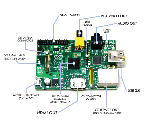
Of course, the “lead actor” on the RPi board is the Broadcom BCM2835, System on a Chip (SoC). Broadcom bills this chip as a “multimedia applications processor for advanced mobile and embedded applications that require the highest levels of multimedia performance”. Maybe more importantly for the DIY/Hacker community is that all the firmware running on the chip is now open source.
There is another big chip, that being the SMSC LAN9512/LAN9512i USB Hub & Ethernet Controller. This is the major work horse in getting data in/out of the RPi for USB peripheral devices and IP networking.
Now note that most of the board’s other large components are for data I/O. Specifically, the HDMI, RCA Video, and Audio Out (3.5mm jack) are output only (at least for general purpose data communication perspective), and therefore, not part of our discussion. On the other hand, the USB and Ethernet ports, are powerful and widely supported serial communication devices, but I will only lightly touch the USB. I want to focus on serial communication with simple/bare-bone devices, like an LCD 16×2 display, which generally are not interface via something as sophisticated at USB or Ethernet. But the USB can be used to some for some types of device interfacing, so I will cover that as a final topic.
There are three other board components that concern themselves with data communications but will not be covered in this post:
- JTAG Header: The JTAG Header is used as a debug port. Embedded systems developer relies on debuggers communicating with chips via the JTAG to perform operations like single stepping and break-pointing. In time, I suspect people will find ways to exploit these pins for both good & evil, but for now, this is for the RPi hardware development community to use.
- CSI Camera Connector: The Camera Serial Interface (CSI) specification is a standard interface between a camera and a host processor for mobile device applications. This will be where you’ll connect cameras and video devices to the RPi.
- DSI Display Connector: The Display Serial Interface (DSI) is a specification aimed at reducing the cost of display sub-systems in a mobile device. This is commonly targeted at LCD and similar display technologies. RPi may be able to interface to some of these. Some graphical LCD/OLED displays might be attached to it. DSI would seem like a good candidate for implementing my LCD display but there is a problem. It appears the DSI isn’t supported at this time.
This leaves one remaining board input/output component standing, that be the General Purpose Input/Output (GPIO). On some electronics boards, GPIO pins have no special purpose defined, and some pins go unused by default. The RPi developer has identified a handful of digital control lines and provided services on them for you to use. By having these available can save you the hassle of having to arrange additional circuitry to provide them or implement functionality in software.
Raspberry Pi’s GPIO as a Data Bus
The first thing to get your head around, is how is data moved around the RPi, or in any general purpose computer. In the most general sense in electronics, a bus or data bus is used to move data words of any type from one place to another. Computing is based on data words made up of collections of data bits. These “words” can contain as few as four data bits and often much larger.
The task of a bus designer is to devise circuitry that passes these data words from one circuit to another. These words can be communicated serially (i.e. serial communications) or in parallel.
- Serial Bus: The least expensive method in terms of wire cost is to send the bits one at a time over a single pair of wires. This is called serial data transmission. Data words start as sets of bits that exist in parallel. In order to ship these words on a serial basis they must be converted to a serial stream of bits at the transmit end and then reconverted to a parallel word at the receive end. The common name for the circuitry that does this conversion is a SerDes circuit which stands for serializer/deserializer. Integrated circuits are more expensive when they have more pins. To reduce the number of pins in a package, many ICs use a serial bus to transfer data when speed is not important. Some examples of such low-cost serial buses include Serial Peripheral Interface (SPI), Inter-Integrated Circuit (I²C), UNI/O, and 1-Wire.
- Parallel Bus: At some point, it is more cost effective to add a wire for each bit in the word and send it in parallel on a data bus. Parallel buses have a limited data rate and distance at which they can be reliably run (more so than a serial bus). Some widely used parallel bus standards are Parallel Bus Interface (PBI), Peripheral Component Interface (PCI), Small Computer Systems Interface (SCSI), the VMEbus used in instrumentation, the Rambus interface used in memories, and others.
As the name implies, GPIO pins can be configured through software to provide some specific function or purpose within the hardware device design. The GPIO pins connect directly into the core of the processor, and the Raspberry Pi developers implemented several alternate functions for the GPIO pins. Several are desirable because of the multiple standards and types of devices you may wish to interface. On boot-up, the RPi board GPIO is in alternate function state “ALT0” and will support I2C, SPI, and UART. This is shown below:

It can be confusing to call the RPi’s whole 26 pin array GPIO and also some specific pins GPIO. In reality, all the GPIO pins can be reconfigured to provide alternate functions.
While PCM isn’t a topic for this posting, in the figure above, you’ll also see references to PCM on pins 18 & 21. PCM stands for Pulse-code modulation and is s a method used to digitally represent analog signals. It is often used to control light intensity or motors. RPi’s native PCM capabilities are not well documented but it appears that people have has some success. Generally, to do anything useful, you need multiple PCM channels so people have resorted to adding hardware or software to get the desired functionality from the RPi. My guess is these RPi pins don’t have much of a future.
I2C, SPI, UART … Say what?
Much has been lightly covered so far, including terms like I2C, SPI, and UART. So what is the significance? Well, I2C, SPI, and UART are the heart of our quest to understand RPi’s serial communications capability. Via their exposure on the GPIO pins, these capabilities are what can be used to integrate things like LCD displays to the RPi. Now lets dive deeper into each one of them.
Universal Asynchronous Receiver/Transmitter (UART)
The Universal Asynchronous Receiver/Transmitter (UART) takes bytes of data and transmits the individual bits in a sequential fashion. The device changes processor’s parallel information to serial data which can be sent on a communication line. A second UART (maybe on another processor) can be used to receive the serial information. The UART performs all the tasks, timing, parity checking, etc. needed for the communication. The only extra devices attached are line driver chips capable of transforming the TTL level signals (0/5 volts) to line voltages (on RS-232 line this could be as +/- 25 volts) and vice versa.
Each UART contains a shift register, which is the fundamental method of conversion between serial and parallel forms. Serial transmission of digital information (bits) through a single wire or other medium is much more cost effective than parallel transmission through multiple wires. The UARTs transmit/receive one bit at a time at a specified data rate (i.e. 9600bps, 115,200bps, etc.). This method of serial communication is sometimes referred to as TTL serial communications.
Asynchronous transmission allows data to be transmitted without the sender having to send a clock signal to the receiver. Instead, the sender and receiver must agree on timing parameters in advance and special bits are added to each word which are used to synchronize the sending and receiving units. When a word is given to the UART for Asynchronous transmissions, a bit called the “Start Bit” is added to the beginning of each word that is to be transmitted. The Start Bit is used to alert the receiver that a word of data is about to be sent, and to force the clock in the receiver into synchronization with the clock in the transmitter.
For a further description of synchronous and asynchronous line communications, check out this tutorial.
Raspberry Pi’s Mini-UART
Warning: Misleading information ahead – See Warren Gay’s comments.
The Raspberry Pi actually has two UARTs. One UART is part of the internal ARM architecture of the Broadcom BCM2835 chip, in the core of the Raspberry Pi and not accessible externally. The other UART is sometimes called the RPi’s “Serial Port” (even thou the USB supports serial communications, and therefore a serial port). The serial port being reference here is serviced by a UART, sometime refereed to as the “Mini-UART” since it doesn’t appear to be very rich in functionality. It is basically be used as a console port for access to the Raspberry Pi. The serial console is a convenient way to interact with the Raspberry Pi for debugging or your network is down and it is the destination of console messages (including boot-up messages). From the Raspberry Pi pinout and the eLinux wiki, I can see that the serial port (aka Mini-UART) on the Pi is on GPIO Pin 14 (TX) and GPIO Pin 15 (RX):
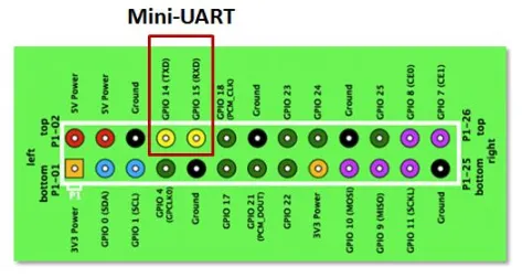
Since the GPIO pins give access to the Mini UART, you can establish a serial console, which can be used to log in to the Pi, and many other things. However, normal console device communicate with -12V (logical “1″) and +12V (logical “0″) RS-232, which may just fry something in the 3.3V Pi. Even “TTL level” serial at 5V runs the same risk. See this tutorial for one example on how to build 3.3V to RS-232 levels converter with a MAX3232CPE and a few passive components.
You can reconfigure the RPi so that the Mini UART isn’t acting as a serial console and use it for outer purposes (e.g. communicate with an attached Arduino or Xbee). Using the Raspberry Pi’s serial port requires some Linux reconfiguration and the abandonment of the serial console, and potentially some level conversion, but it could be useful. The Mini-UART pins to provide access to Linux’s /dev/ttyAMA0 serial port. To be able to use the serial port to connect and talk to other devices, the serial port console login needs to be disabled and the post “Raspberry Pi and the Serial Port” shows you how.
Again, keep in mind that RX and TX lines are available on the GPIOs but operate at 3.3 volts. You’ll need a board or cable to level convert 3.3 volt UART signals to connect with other devices (e.g. RS-232, USB).
Serial Peripheral Interface Bus (SPI) — aka 4-Wire Serial Bus
The Serial Peripheral Interface Bus or SPI (pronounced as either S-P-I or spy) bus is a synchronous serial data link standard, named by Motorola, that operates in full duplex mode. SPI is much simpler than I2C. Master and slave are linked by three data wires, usually called MISO, (Master in, Slave out), MOSI (Master out, Slave in), the SCLK clock line (sometimes called M-CLK), and an optional SS (Slave Select; sometimes known as the Chip Select or CS line or Chip Enable or CE line) is the slave select or chip select line. Its optional only if you have one slave, otherwise one or more SS lines are provided. The Raspberry Pi has two Slave Select lines: CE0 and CE1.

Usually the transfer sequence consist of driving the SS line low, sending X number of clock signals with the proper polarity and phase, then driving the SS line high to end the communication. As the clock signals are generated, data is transferred in both directions, therefore in a “transmit only” system the received bytes have to be discarded and in a “receive only” system a dummy byte has to be transmitted.
Many SPI-enabled ICs and Microcontrollers can cope with data rates of over 10MHz, so transfer is much faster than with I2C. Since it is synchronous communications, it is not limited to 8-bit words so you can send any message sizes with arbitrary content and purpose. The SPI interface does not require pull-up resistors, which translates to lower power consumption. The downside is that SPI normally has no addressing capability; instead, devices are selected by means of a SS signal which the master can use to enable one slave out of several connected to the SPI bus. If more than one slave exists, one chip select line is required per device, which can use precious GPIO lines on the Master.
Inter-Integrated Circuit (I2C) — aka 2-Wire Serial Bus
Inter-Integrated Circuit or I2C (pronounced as either I-squared-C or I-2-C) is generically referred to as a “two-wire interface”. It’s a multi-master serial single-ended computer bus invented by Philips that is used to attach low-speed peripherals to a motherboard, embedded system, cellphone, or other electronic device.
I2C can be used to connect up to 127 nodes via a bus has two data wires, called SCL and SDA. SCL is the clock line. It is used to synchronize all data transfers over the I2C bus. SDA is the data line. Of course, there is a third wire being ground. There may also be a 5 volt wire to distribute power to the devices. Both SCL and SDA lines are “open drain” drivers. What this means is that the chip can drive its output low, but it cannot drive it high. For the line to be able to go high you must provide pull-up resistors to the 5v supply. There should be a resistor from the SCL line to the 5v line and another from the SDA line to the 5v line. The value of the resistors is not critical. Anything from 1800 ohms to 47K ohms used (1.8K, 47K and 10K are common values). You only need one set of pull-up resistors for the whole I2C bus, not for each device, as illustrated below:

In theory the I2C bus can support multiple masters, but most micro-controllers can’t. A master is usually a microcontroller, although it doesn’t have to be. Slaves can be ICs or microcontrollers. When the master wishes to communicate with a slave it sends a series of pulses down the SDA and SCL lines. The data that is sent includes an address that identifies the slave with which the master needs to interact. Addresses take 7 bits out of a data byte; the remaining bit specifies whether the master wishes to read (get data from a slave) or write (send data to a slave).
Some devices have an address that is entirely fixed by the manufacturer; others can be configured to take one of a range of possible addresses. When a micro-controller is used as a slave it is normally possible to configure its address by software, and for that address to take on any of the 127 possible values. The address byte may be followed by one or more byes of data, which may go from master to slave or from slave to master.
When data is being sent on the SDA line, clock pulses are sent on the SCL line to keep master and slave synchronised. Since the data is sent one bit at a time, the data transfer rate is one eighth of the clock rate. The original standard specified a standard clock rate of 100KHz, and most I2C chips and micro-controllers can support this. Later updates to the standard introduced a fast speed of 400KHz and a high speed of 1.7 or 3.4 MHz. The Arduino and Raspberry Pi can support standard and fast speeds.
The fast rate corresponds to a data transfer rate of 50K bytes/sec which is too slow for some control applications. One option in that case is to use SPI instead of I2C.
1-Wire — aka 1-Wire Serial Bus
On a 1-Wire bus (sometime refered to as a “MicroLan”), a single master device communicates with one or more 1-Wire slave devices over a single data line, which can also be used to provide power to the slave devices. Devices drawing power from the 1-wire bus are said to be operating inparasitic power mode. When operating in parasite power mode, only two wires are required: one data wire, and ground. At the master, a 4.7k pull-up resistor must be connected to the 1-wire bus. With an external supply, three wires are required: the bus wire, ground, and power. The 4.7k pull-up resistor is still required on the bus wire.

Each 1-Wire device contains a unique 64-bit code, consisting of an 8-bit family code, a 48-bit serial number, and an 8-bit CRC. Before sending a command to a slave device, the master must first select that device using its code.
How do you use I2C, SPI, UART, or 1-Wire on the Raspberry Pi?
Now that we know the what & why for serial communications options on the Raspberry Pi, how do we use them? This topic deserves technical details and examples but this post has already run too long. I’m likely to do some specific implementation in the future, but for now I’ll reference some sources of information on the web.
First, lets be clear about the RPi software distribution I’m using, since not all will be supporting all these serial communications options. I’m using Adafruit’s Occidentalis distribution (based on “Wheezy”) which comes with hardware SPI, I2C, and 1-wire support. In the Occidentalis distribution, Adafruit has included in the Linux kernel the needed drivers. SPI and I2C has been implement on the GPIO pins as outline above. RPi doesn’t have a predetermined GPIO pin assignment for 1-Wire, but Adafruit choose GPIO pin 4 for 1-Wire. Note that this unassigned GPCLK0 (General Purpose Clock Voltage) function.
Given you have the Occidentalis distribution, you can check on the installation of I2C, SPI, and 1-Wire via the following:
- To validate I2C, connect any I2C device to power, ground, SDA and SCL. Then run
sudo i2cdetect -y 0to detect which addresses are on the bus.i2cdetectis a program to scan an I2C bus for devices. Also, you can list the I2C device drivers via the commandls /dev/*i2c*. This illustrates that RPi supports two I2C buses, 0 and 1. - To validate SPI, the command
ls /dev/*spi*will list two SPI devices, one each for the 0 & 1 SS lines. To go further, use the spidev_test.c tool described in Getting SPI working on the Raspberry Pi. - Occidentalis implementation of 1-Wire isn’t done via a kernel installed driver but bitbanged. Adafruit states that the implementation is “flakier than SPI or I2C” and they don’t have any tutorials. Maybe 1-Wire should be shelved for now.
There are some good RPi SPI & I2C tutorials on Adafruits. There are others on personal blogs but generally they are scares right now.
Attach Peripherals to the Raspberry Pi
Now that we know the in’s & out’s of serial communications with the RPi, what can be done to make the physical aspects of interfacing the board easier. Dealing with the GPIO pins on the board can be a pain. One solution is the Pi Cobbler which plug the GPIO pins into a solderless breadboard via a ribbon cable. My personal favorite is the Pi Crust. In this case, the confusing layout of GPIO pins are much more clearly organized and supplied with more useful female headers. A whole development environment will be supplied via PiFace Digital and Gertboard … when they become available.
The USB Serial Ports
As promised, the final topic is the USB port. The USB can be used for some types of device interfacing, particularly if you make it look like a simple serial port to the device. The conventional serial port (not the newer USB port) is a very old I/O (Input/Output) port. It’s slow compared to newer Universal Serial Bus (USB) serial devices, but conventional serial ports are still in use and many devices you’ll hook to your RPi will want to use them. Until around 2006, most new desktop PC’s had one but has been largely replaced by the USB. Conventional serial ports are still widely used in embedded systems, but the RPi choose to use the USB. Never the less, it is possible to put a conventional serial port device on the USB bus by using a Serial to USB Adapter hardware or cables. This could be necessary for some of the hardware hacking you’ll do with an RPi. (For example, I’ll be posting a project where I’ll use the RPi’s USB to talk to a XBee radio.)
USB does synchronous communications (synchronous means that bytes are sent out at a constant rate one after another in step with a clock signal tick) and transmits in special packets like a network. Conventional serial ports are typically asynchronous (i.e. “not synchronous”). Just like a network, USB can have several devices physically attached to it, including serial ports. Each device on it gets a time-slice of exclusive use for a short time. A device can also be guaranteed the use of the bus at fixed intervals. One device can monopolize it if no other device wants to use it.
Under Linux, each and every hardware device, including USB ports, are treated as a file and call a device file. A device file allows a user to access hardware devices, but shields the users from the technical details about the hardware. (This is unlike what we’ll see for the RPi GPIO interfaces where hardware level technical details must be address directly.) Under Linux, a conventional serial port will typically have a device file such as /dev/ttyS0, /dev/ttyS1, etc. but the USB serial ports will appear as /dev/ttyUSB0, /dev/ttyUSB1, etc. When your device is plugged in, Linux assigns the filename as it sees fit and isn’t always predicable (it doesn’t have to be this way). If you need to know what device file your serial device is connected too (and your software often needs to know), using a combination of the commands lsusb, dmesg, and grep, plus some basic insight, will often do the trick.
The lsusb command can show you the hubs connected to your system, but you won’t necessarily see any entries in /dev until you plug something into it, and what that entry may be will be dependent upon the type of device you are plugging in. The system doesn’t recognize new USB devices right away. It can take from a couple of seconds to as much as a minute. If I plug my Serial to USB Adapter cable, using the lsusb command I can identify the cables . Now using dmesg, and grepping for the “Manufacturer”, I can get the “FTDI”. Now I grep again for “FTDI” to get the device file name “ttyUSB0“. This is all illustrated below:

Speech Synthesis on the Raspberry Pi
Now that I can get sound out of my Raspberry Pi (RPi), the next logical step for me is speech synthesis … Right? I foresee my RPi being used as a controller/gateway for other devices (e.g. RPi or Arduino). In that capacity, I want the RPi to provide status via email, SMS, web updates, and so why not speech? Therefore, I’m looking for a good text-to-speech tool that will work nicely with my RPi.
The two dominate free speech synthesis tools for Linux are eSpeak and Festival (which has a light-weight version called Flite). Both tools appear very popular, well supported, and produce quality voices. I sensed that Festival is more feature reach and configurable, so I went with it.
To install Festival and Flite (which doesn’t require Festival to be installed), use the following command:
sudo apt-get install festival
sudo apt-get install flite
Festival
To test out the installation, check out Festival’s man page, and execute the following:
echo "Why are you in front of the computer?" | festival --tts
date '+%A, %B %e, %Y' | festival --tts
festival --tts Gettysburg_Address.txt
Text, WAV, Mp3 Utilities
Festival also supplies a tool for converting text files into WAV files. This tool, called text2wave can be executes as follows:
text2wave -o HAL.wav HAL.txt
aplay HAL.wav
MP3 files can be 5 to 10 times smaller than WAV files, so it might be nice to convert a WAV file to MP3. You can do this via a tool called lame.
lame HAL.wav HAL.mp3

Flite
Flite (festival-lite) is a small, fast run-time synthesis engine developed using Festival for small embedded machines. Taking a famous quote from HAL, the computer in the movie “2001: A Space Odyssey”
flite "Look Dave, I can see you're really upset about this. I honestly think you ought to sit down calmly, take a stress pill, and think things over."
Depending how the software was built for the package, you find that flite (and festival) has multiple voices. To find what voices where built in, use the command
flite -lv
To play a specific voice from the list, use the -voice parameter in the command
flite -voice kal "I'm now speaking kal's voice. By the way, please call me Dr. Hawking."
In my case, the default voice appears to be “kal”, which sounds somewhat like Stephen Hawking. “slt” appears to be a female version of the “kal” voice.
flite_time is a talking clock that can speak things like “The time is now, exactly two, in the afternoon.”
flite_time 14:00
flite_time `date +%H:%M`
Documentation
The documentation for Festival and Flite isn’t all that great but there does seem to be multiple sources. Here is what I found most useful:
Getting Audio Out Working on the Raspberry Pi
I want to deliver sound from my Raspberry Pi’s (RPi) Audio Output 3.5mm jack. I’ll need to get audio drivers working on Audio Out, and to test it, I’ll need some sound files and players. I’m choosing the Advanced Linux Sound Architecture (ALSA) drivers because its widely supported and because ALSA not only provides audio but Musical Instrument Digital Interface (MIDI) functionality to Linux. I’ll also be using the popular command line MP3 players, mpg321 and the WAV player that comes with ALSA, aplay.
To get things going, I installed ALSA, a MP3 tools, and a WAV to MP3 conversion tool via the following commands:
sudo apt-get install alsa-utils

sudo apt-get install mpg321

sudo apt-get install lame
Enabling the Sound Module
Reboot the RP and when it comes back up, its time to load the Sound Drivers. This will be done via loadable kernel module (LKM) which are object file that contains code to extend the Linux kernel. lsmod is a command on Linux systems which prints the contents of the /proc/modules file. It shows which loadable kernel modules are currently loaded. In my case, lsmod gives me:

The snd-bcm2835 module appears to be already installed. RPi has a Broadcom BCM2835 system on a chip (SoC) which is a High Definition 1080p Embedded Multimedia Applications Processor. snd-bcm2835 is the sound driver. If lsmod doesn’t list the snd-bcn2835 module, then it can be installed via the following command:
sudo modprobe snd-bcm2835
Enabling Audio Output
By default, the RPi audio output is set to automatically select the digital HDMI interface if its being used, otherwise the analog audio output. You can force it to use a specific interface via the sound mixer controls. amixer allows command-line control of the mixer for the ALSA driver.
You can force the RPi to use a specific interface using the command amixer cset numid=3 N where the N parameter means the following: 0=auto, 1=analog, 2=hdmi. Therefore, to force the Raspberry Pi to use the analog output:
amixer cset numid=3 1
Sound Check
With this done, you should be ready for a simple test. Plug a speaker into the (RPi) Audio Output 3.5mm jack. I used a simple battery powered iHM60 iHome speaker. The jack will not deliver much power, so the speaker needs to be powered.
To test the RPi audio, you can play a WAV file (download this … excellent for user-error notification) with aplay, mpg321 for MP3 files, or use the speaker-test command if you don’t have a WAV/MP3 file.
aplay numnuts.wav
speaker-test -t sine -f 440 -c 2 -s 1
mpg321 "Mannish Boy.mp3"
More on the ALSA Sound Drivers and Utilities
While ALSA is a powerful tool, it documentation appears is very weak. Also, it appears that the capabilities of ALSA drivers and utilities are very dependent on the hardware used. The best sources of documentation that I found include Advanced Linux Sound Architecture (ALSA) project homepage, archlinux Advanced Linux Sound Architecture, and ALSA-sound-mini-HOWTO.
You can find useful information in the directory /proc, which is a “virtual” file system (meaning that it does not exist in real life, but merely is a mapping to various processes and tasks in your computer).
/proc/modulesgives information about loaded kernel modules. The commandlsmod | grep sndwill list modules relevant to the sound system.- You can check the existence of a soundcard by looking at
cat /proc/asound/cards.
The amixer command can provide useful information (sometimes):
- You can look at the mixer settings by typing
amixerwithout any arguments. This command lists the mixer settings of the various parts of the soundcard. The output fromamixercan greatly differ from card to card. Unfortunately you can’t find much documentation on how to interpret the out. - The RPi doesn’t have a “Master” control only “PCM”. So commands like
amixer set Master...will not work. You must useamixer set PCM ... - You can mute /unmute the sound via these commands:
amixer set PCM muteandamixer set PCM unmute - As of August 2012, there appears to be a known bug in RPi ALSA driver that ignores volume settings at the start of playback and always plays at max volume. Therefore, commands like
amixer set PCM 50% unmutewill not set the volume to 50%, at least until this bug is fixed. Maybe this isn’t really a bug but a limitation of the hardware because there is a workaround for this …. see below.
Volume Control
The RPi built-in sound chips don’t have a “master volume” control, and as a result, you must control the volume via software. I guess the RPi views itself as a preamplifier (preamp) and volume controls would be supplied down stream. ALSA provides a software volume control using the softvol plugin.
The /etc/asound.conf file is a configuration files for ALSA drivers (system-wide). The main use of this configuration file is to add functionality. It allows you to create “virtual devices” that pre or post-process audio streams. Any properly written ALSA program can use these virtual devices as though they were normal devices. My RPi /etc/asound.conf file looks like this:

For most changes to /etc/asound.conf you will need to restart the sound server (ie. sudo /etc/init.d/alsa-utils restart) for the changes to take effect.
I attempted to implement the software volume controls outline in a softvol how-to that I found, but I couldn’t get it to work. I did some additional digging, and I found a solution buried within a python script for a Adafruit project. The following works for controlling the volume (in this case, reducing the volume to 80% of maximum):
amixer cset numid=1 -- 80%
Note that you can use this command to change the volume while sound is being played an its effect takes place immediately. Also, I noticed that once the volume has been adjusted, its effect remains even after a reboot.
WAV and MP3 Conversion
The MP3 player mpg321 can convert MP3 files to WAV files but the WAV player, aplay, can not do a conversion. To make a MP3 file from a WAV file, you’ll need the tool lame.
- To convert from WAV to MP3:
lame input.wav output.mp3 - To convert from MP3 to WAV:
mpg321 -w output.wav input.mp3
Bottomeline
While you can get ALSA working on the Raspberry Pi, it appears only partly supported, maybe buggy, and poorly documented. If you just want to simply get sound out of the device (like I do), you’ll be fine. But if you have some desire to do some sound processing with ALSA, your likely to be very frustrated.
Epilogue
This specific post has gotten about 25% of all the viewings of my blog. I’m not sure why this is the case but I speculate that there are many people tying to make RPi into a Media Player and looking for answers to their technical problems.
At this point in time, others have done some additional postings and they are more instructive than my post. You should check out:
Dropbox for the Raspberry Pi (sort of)
I’m presently using Dropbox as a service for quick & easy movement of files between multiple PCs I use. Its copy & paste operation is very intuitive on a Windows PC. I would like the same on the Raspberry Pi (RPi), particularly for moving files from my PC to the RPi. I wanted the same utility on my RPi, but at the same time, I want the Linux command line paradigm supported and not be force to run X Windows on the RPi.
I did some searching and found things like Dropbox’s Linux distribution (which I wasn’t confident would work “out of the box” for the RPi’s ARM architecture, but source is provided), GoodSync or Owncloud (which wouldn’t access my existing Dropbox files but instead create an alternative), python or bash shell based up/down loaders (appears to behave like a simplified FTP tool), or the Secure SHell File System (SSHFS) based approach (the PC’s Dropbox directory is mounted on the RPi).
While the Dropbox’s Linux distribution is likely the ultimate way to go, I didn’t want to commit myself to the effort it would potentially require. I settled on the SSHFS based approach. I’m running my RPi headless and access it via my PC using Cygwin/X and Secure Shell (ssh). With the SSHFS approach, I could make the Dropbox directory available for mounting at boot-up or mount it at will. I only envision using the RPi-based Dropbox when I’m doing development and I will be doing that from my PC. So this SSHFS approach seems fine for the way that I operate.
The SSHFS approach means files will not really be replicated on the RPi, like Dropbox does. The files will reside within my PC’s Dropbox folder (and replicated on my other PCs via the Dropbox service) but accessible by the RPi via the SSHFS file mount. This means I can’t have any applications I run on the RPi depend on files located in its Dropbox directory since it may not be always mounted. I’m OK with this limitation, and in fact is consistent with the ad-hoc purpose I have for the Dropbox directory.
Installation Required on the PC
For me, nothing needs to be done here. I already have Dropbox running on my PC, and via Cygwin/X, I have the foundations required for the host side of the SSHFS solution. If you need help with this, signup for Dropbox here and find out how I’m using Cygwin/X here.
Installation Required on the RPi
On the client side of the solution, you’ll need to install SSHFS and FUSE. FUSE is the user-space filesystem framework and is the foundation on which SSHFS resides. FUSE allows user-space software, SSH in this case, to present a virtual file system interface to the user; something generally only done by the Linux kernel. SSHFS connects to the remote system and provide the look and feel of a regular file system interface for remote files. On the RPi, install SSHFS via the command:
sudo apt-get install sshfs
FUSE appear to be already installed on the RPi or maybe comes with SSHFS. Next you need to add required users to the FUSE usergroup. In my case, that is the user pi. You can see the existing groups pi is part of via the command groups pi. You can validate that the FUSE user group has been created by using the command cat /etc/group | grep fuse. To add pi to the FUSE user group, use the command:
sudo gpasswd -a pi fuse
The fuse group lets you limit which users are allowed to use FUSE-based file systems, in my case the Dropbox. This is important because FUSE installs setuid programs, which always carry security implications.
Configuring the Dropbox File System
Now its time to make your Dropbox directory on the RPi, and mount it to the PC’s instance of Dropbox. On the RPi, use this command to create the Dropbox:
mkdir ~/Dropbox
The next thing to do is to make sure that you can connect to the PC via ssh. When I installed Cygwin, my focus was on using it as an X Server and making ssh connections from the PC to RPi. I never tried the inverse (connect from the RPi to the PC) and that is what SSHFS is effectively doing. So check for two things:
- Is the ssh server running on the PC? You can check for its status via the command
cygrunsrv -Q sshd. In my case it was running, so its fine. - Is the port used by the ssh server on the PC open? You’ll need to open SSH port 22 for ssh services to work. You can check its status by attempting to use it. In my case, this was
ssh Jeff@HomePC.home. If this command appears to hang or time out (as it did for me), the port is likely blocked. You’ll need to go to your Windows Firewall and open port 22.
There is another Cygwin sublimity that has to be taken into consideration. When using the Cygwin, Windows drive letters are mapped to a special directory. In my case, the Dropbox directory appears to Cygwin to have the following path: /cygdrive/c/Users/Jeff/Dropbox.
With this all addressed, reboot the RPi, and then you can now fire up you RPi Dropbox via:
sshfs Jeff@HomePC.home:/cygdrive/c/Users/Jeff/Dropbox ~/Dropbox
After you supply the PC’s password, you should now be able to access the Dropbox directory on the PC. If you wish, you can remove the file system connection to the PC via the command:
fusermount -u ~/Dropbox
This connection will stay established as long as you don’t do the fusermount -u or reboot the RPi. If you wish to mount the file system upon boot-up, and avoid executing the sshfs when you log-in, you can follow the procedure outline in the article that initially inspired me: Dropbox on Raspberry Pi via SSHFS
Something to Keep in Mind
While for the most part, moving between Windows/DOS and the Linux file systems isn’t a problem, there is one thing to remember. Windows-based text editors put one set of special characters at the end of lines (i.e. carriage return and line break = ‘\r\n’), while Unix/Linux puts other characters (i.e. line break = ‘\n’). This odd anomaly is normally harmless, but some applications on a Linux cannot understand these characters and can cause Linux to not respond correctly.
The best example of Linux behaving badly (and the only one I know) is the execution of “shebang” or the “#!…” at the top of a bash, python, perl, etc. script. If you edit these files in DOS, then move them to Linux, shebang will stop working. Editing them under DOS is the origin of the problem, since a DOS based text editor will inject the extra carriage return character at the end of the text line.
To fix this problem, you can quickly convert an ASCII text file from DOS format (carriage return and line break) to the Unix format (line break), you can use the tool dos2unix. Run this utility on the effected file and shebang should work once again.
Epilogue
At its foundation, SSH functions as a protocol for authenticating and encrypting remote shell sessions. SSH can be thought of as much more than just a secure shell. Using SSH’s foundation, SSHFS creates a new capability. To learn more, check out the link SSH: More than secure shell.
Key sources I consulted to write this include:
SendEmail as a Messaging Tool for the Raspberry Pi
In the projects I envision for the future, I’ll be using my Raspberry Pi (RPi) as a gateway/server/controller for several other devices. There is likely to be a need to generate status reports/messages and mail them out. It could be as simple as a notification that the deck lights have been turned-on. I don’t need a full fledged mail client on the RPi to receive mail or manage a mailbox, just a command line utility to send email. Also, I would like to send short text messages via (SMS) to my cell phone. Linux does have a nice solution for this.
You do need an established email account with some email provider. I want to keep my personal email and my RPi’s email separate so I setup a special email account on gmail. This will be used only by my Raspberry Pi’s (or other intelligent devices). There exist some open SMTP relay mail servers (mail servers that will not require a login nor a password) but many open mail relays have become unpopular and closed due to their exploitation by spammers and worms.
SendEmail
SendEmail is a lightweight, completely command line based, SMTP email agent. It is written in Perl and designed to be used on the command line, in bash scripts, Perl programs, within web sites, etc.
I installed SendEmail on my RPi via this command:
sudo apt-get install sendemail
Testing sendEmail
When I ran sendEmail the first time, it complained about some missing libraries. I installed the missing libraries and this cleared the error. Clearly, the sendEmail package needs some work since this dependency should have been taken care of by apt-get.
I ran it again using this command:
sendEmail -f pi@RedRPi -t my_user_name@verzion.net -u "Test Email from RedRPi" -m "My test message." -s smtp.gmail.com:587 -o tls=yes -xu my_user_name -xp my_password
With this, sendEmail threw an error message:
invalid SSL_version specified at /usr/share/perl5/IO/Socket/SSL.pm line 332
I did a web search and found that this is a reported bug within sendEmail (bummer), but I also found a simple patch for the problem (lucky break). I applied the fix, executed the command again, and succeeded in sending the email.
One of the key parameter used here is the SMTP mail relay specified in “-s smtp.gmail.com:587“. In this case, Gmail uses port 587 for relay email. The default port to use is 25 but not all email servers use this port.
Another key parameter is “-o tls=yes“. This specifies that the Transport Layer Security (TLS) protocol will be used to provide communication security over the Internet. This is important since your including a plain-text password in the command.
SMS Messaging
Another messaging mechanism that I plan to use is Short Message Service (SMS). To do this, you can use a SMS gateway which will transform an email into an SMS message. The down side is that there isn’t a single gateway but one for each of the cellular carries.
Here is an example for AT&T cell phones:
sendEmail -f pi@RedRPi -t cell_phone_number@txt.att.net -u "Test Email from RedRPi" -m "My test message." -s smtp.gmail.com:587 -o tls=yes -xu my_user_name -xp my_password
WiFi (with WEP security) on Raspberry Pi
The Raspberry Pi Linux distribution I’m using is Adafruit’s Occidentalis. It supports WiFi out of the box and appears easy to configure. But as noted by Adafruit, adding peripherals to the RPi may increase the loading on the power supply to your board and this, in turn, may affect the voltage presented to the RPi.
This is clearly the case, even for the tiny OURlink WiFi (802.11b/g/n) USB Adapter (uses the RTl8192cu chip which is supported by Debian Linux) I purchased from Adafruit. When I plugged it into the RPi, it became unstable and crashed. Adafruit advises that you can over come this by attach the RPi’s USB port to a powered hub. (Note that all USB hubs aren’t powered or powered sufficient, and therefore, not all are recommended. I used a Dynex 4 Port Hub with a 5V 2.1A power adapter and all seem fine.) If you find using a using a USB hub completely unacceptable, you could make some RPi board modifications to the polyfuses, but this isn’t the “official/supported” approach for this power problem …. but first …. see the Epilogue below.
My First Attempt (Unsuccessful)
Once I got the RPi USB port properly powered, I followed the Adafruit’s instructions. I updated the/etc/network/interfaces file with the following:
########## DID NOT WORK FOR ME ##########
# The loopback network interface
auto lo
iface lo inet loopback

# The primary (wired) network interface
iface eth0 inet dhcp

# The wifi (wireless) network interface
auto wlan0
allow-hotplug wlan0
iface wlan0 inet dhcp
     wpa-ssid YOUR_SSID
     wpa-psk YOUR_WEP_KEY
I ran ifconfig -a and got the following:

This tells me that Linux sees the WiFi device and assigned it device name wlan0. It also says there isn’t an IP address assigned and no data is moving. Appears that network interface wlan0 isn’t running so I tried bring it up with sudo ifup wlan0 and I got the following:

No IP assigned … now what?
This Worked … But
After the typical thrashing about, it came to me that I’m not using WAP security (which is implied by the/etc/network/interfaces file content) but I’m using WEP. I did some web searching and found a site that claimed to address Debian WiFi WEP configuration. This provided me the needed command syntax for the solution. I updated the/etc/network/interfaces file with the following:
# The loopback network interface<
auto lo
iface lo inet loopback

# The primary (wired) network interface
iface eth0 inet dhcp

# The wifi (wireless) network interface
auto wlan0
allow-hotplug wlan0
iface wlan0 inet dhcp
       wireless-essid YOUR_SSID
       wireless-key YOUR_WEP_KEY
I then ran sudo ifup wlan0 to start the wireless networking (Note: you can use sudo ifdown wlan0 to turn-off the wireless network). This time DHCP discovery appeared to work. I then ran ifconfig -a giving me the display below with an assigned wireless IP.
")
The wireless device now has an IP address and data seems to be flowing. In an effort to further convince myself that the WiFi was working, I disconnected the wired ethernet connection and attempted to re-login in via ssh -X pi@RedRPi.local, over the wireless interface. This failed, giving the message:
ssh: Could not resolve hostname RedRPi.local: hostname nor servname provided, or not known
Working For Sure
I suspected (after more thrashing about) it was Ssh or Avahi/Bonjour or both that was getting in the way. So I did the following:
- I cleaned out the
~/.ssh/known_hostsfile on the PC from which I’m accessing the RPi (I’m using Cygwin with Openssh). With the entries in the file removed ssh keys would need to be recreated on next login. - I then logged into the RPi in via
ssh -X pi@RedRPi.local.The login created an entry the~/.ssh/known_hostsfile on the PC. - Using vi, I edited the
~/.ssh/known_hostsfile. I duplicated the one existing record but changed the IP address to the wireless address. - I restarted the openssh on the PC. (I terminated all the Cygwin window and restarted them. I could get anything else to work short of a PC reboot).
- I then logged in using
ssh -X pi@192.168.1.7. Now I’m wireless!!
My ~/.ssh/known_hosts file looks like this:

Epilogue
I have found that if I don’t use a USB powered hub and I plug in the OURlink WiFi (802.11b/g/n) USB Adapter while the RPi is up and running, the RPi will crash. The good news is that, once the RPi reboots, it runs fine without the powered hub.
So, go ahead and use the WiFi USB Adapter, without the powered hub, but make sure the adapter is plugged in when you boot up …. problem solved!
Conky for the Raspberry Pi
 Conky is a Linux system monitor tool using X Windows. Conky is highly configurable and is able to monitor many system variables including the status of the CPU, memory, swap space, disk storage, temperatures, processes, network interfaces, battery power, system messages, e-mail in-boxes Linux updates, runs many popular music players, and much more. Unlike system monitors that use high-level widget tool-kits to render their information, Conky is drawn directly in an X window, allowing it to consume relatively fewer system resources.
To install the standard Conky package, use the following:
sudo apt-get install conky-std
Two sites you will want to read, beyond the Conky manual page are the lists of Config Settings and Variables. You use the Config Settings to describe general features of how you want your Conky to appear, and the variables to define what actually gets displayed.
The color names that are used within Conky are the X11 colors located in /usr/share/X11/rgb.txt. There isn’t a standard set of colors to be found on any X Window system, so you’ll need to inspect this file to get some idea of what color names you can use. This X color name list, which appears to be larger than what is in the RPi’s rgb.txt file, could help you visualized the colors.
Conky uses a configuration file location in $HOME/.conkyrc. Conky can be configured in an amazing number of way but I’m using the following configuration on the RPi:
# --------------------------------------------------------------------------------------------- #
#
# .conkyrc - derived from various examples across the 'net
#
# Some of the sites that proved most usful include:
#   http://mylinuxramblings.wordpress.com/2010/03/23/how-to-configure-the-conky-system-monitor/`
#   http://crunchbanglinux.org/wiki/conky
#   http://lusule.wordpress.com/2008/08/07/how-to-4/
#
# --------------------------------------------------------------------------------------------- #

# -------------------- Conky's Run Time Parameters -------------------- #

update_interval 2.0                     # Conky update interval in seconds
total_run_times 0                       # Number of updates before quitting.  Set to zero to run forever.
no_buffers yes                          # Subtract file system buffers from used memory?
cpu_avg_samples 2                       # Number of cpu samples to average. Set to 1 to disable averaging
net_avg_samples 2                       # Number of net samples to average. Set to 1 to disable averaging

# -------------------- Conky's General Look & Feel -------------------- #

# --- defualt values --- #
default_color grey                      # Default color and border color
default_bar_size 0 6            # Specify a default width and height for bars.
default_gauge_size 25 25        # Specify a default width and height for gauges.
default_graph_size 0 25         # Specify a default width and height for graphs.
default_outline_color green     # Default border and text outline color
default_shade_color yellow      # Default border and text shading color

# --- predefined colors - http://www.kgym.jp/freesoft/xrgb.html --- #
color0 FFFFFF                           # white
color1 FFA500                           # orange
color2 B22222                           # firebrick
color3 696969                           # dim gray
color4 D3D3D3                           # light gray
color5 2F4F4F                           # dark slate gray
color6 FFEC8B                           # light golden rod
color7 54FF9F                           # sea green
color8 FF8C69                           # salmon
color9 FFE7BA                           # wheat

# --- window layout & options --- #
own_window yes                          # Conky creates its own window instead of using desktop
own_window_type normal          # If own_window is yes, use type normal, desktop, or override
own_window_transparent yes      # Use pseudo transparency with own_window?
own_window_colour blue          # If own_window_transparent is no, set the background colour
double_buffer yes                       # Use double buffering (reduces flicker)
use_spacer right                        # Adds spaces to stop object from moving
maximum_width 600                       # Maximum width of window in pixels
own_window_hints undecorated,below,sticky,skip_taskbar,skip_pager

# --- window placment --- #
alignment top_right

# --- borders, margins, and outlines --- #
draw_graph_borders yes          # Do you want to draw borders around graphs
border_inner_margin 9           # Window's inner border margin (in pixels)
border_outer_margin 5           # Window's outer border margin (in pixels)
gap_x 10                                        # Gap between borders of screen and text (on x-axis)
gap_y 40                                        # Gap between borders of screen and text (on y-axis)
border_width 10                         # Window's border width (in pixels)

# --- Text --- #
draw_outline no                         # Do you want ot draw outlines
draw_shades no                          # Do you want to draw shades
draw_borders no                         # Do you want to draw borders around text
uppercase no                            # set to yes if you want all text to be in uppercase
use_xft yes                                     # use the X FreeType interface library (anti-aliased font)
xftfont Monospace:size=8:weight=bold    # Xft font to be used

# -------------------- Conky's Displayed System Monitoring Parameters -------------------- #
TEXT
# Title / Banner message
${color5}
${alignc 40}${font Arial Black:size=22}${time %H:%M:%S}${font}
${alignc}${time %A} ${time %B} ${time %d}, ${time %Y}
$color

# General system information
${color1}SYSTEM INFORMATION ${hr 2}$color
${color0}System: $color$nodename ${alignr}${color0}Uptime: $color$uptime
${color0}Kernel: $color$kernel${alignr}${color0}Arch: $color$machine
${color0}Frequency: $color$freq MHz
${color0}Serial No.: $color${execi 99999 grep Serial /proc/cpuinfo | awk '{ print $3 }'}
${color0}MAC Address: $color${execi 99999 cat /sys/class/net/eth0/address }

# CPU information
${color1}CPU ${hr 2}$color
${color0}Avg. Load: $color $loadavg
${color0}CPU Temperature: $color${acpitemp}°C
${color0}CPU Usage:$color $cpu% ${color7}${cpubar}
${cpugraph 0000ff 00ff00}$color

# Top running processes
${color1}TOP 5 PROCESSES ${hr 2}$color
${color0}Processes:$color $processes  ${color0}Running:$color $running_processes
${stippled_hr 2}
${color0}CPU Usage$color
${color3} NAME              PID    CPU %   MEM$color
${color2} ${top name 1} ${top pid 1} ${top cpu 1} ${top mem 1}$color
 ${top name 2} ${top pid 2} ${top cpu 2} ${top mem 2}
 ${top name 3} ${top pid 3} ${top cpu 3} ${top mem 3}
 ${top name 4} ${top pid 4} ${top cpu 4} ${top mem 4}
 ${top name 5} ${top pid 5} ${top cpu 5} ${top mem 5}
${stippled_hr 2}
${color0}Mem Usage$color
${color3} NAME              PID    CPU %   MEM$color
${color2} ${top_mem name 1} ${top_mem pid 1} ${top_mem cpu 1} ${top_mem mem 1}$color
 ${top_mem name 2} ${top_mem pid 2} ${top_mem cpu 2} ${top_mem mem 2}
 ${top_mem name 3} ${top_mem pid 3} ${top_mem cpu 3} ${top_mem mem 3}
 ${top_mem name 4} ${top_mem pid 4} ${top_mem cpu 4} ${top_mem mem 4}
 ${top_mem name 5} ${top_mem pid 5} ${top_mem cpu 5} ${top_mem mem 5}

# Memory and swap space untilization
${color1}MEMORY & SWAP ${hr 2}$color
${color0}RAM Usage: ${color}$mem / $memmax
$memperc% ${color6}${membar}$color
${stippled_hr 2}
${color0}Swap Usage: ${color}$swap / $swapmax
$swapperc% ${color6}${swapbar}$color

# File System utilization
${color1}FILE SYSTEM ${hr 2}$color
${color0}SD Card:$color ${fs_used /} / ${fs_size /}
${fs_used_perc /}% ${color8}${fs_bar /}$color
${stippled_hr 2}
${color0}Reads: $color$diskio_read/s${alignr}${color0}Writes: $color$diskio_write/s
${color8}${diskiograph_read 20,100 33FF00 FF3333 scale -t}$color${alignr}${color8}${diskiograph_write 20,100 33FF00 FF3333 scale -t}$color

# Ethernet utilization
${color1}NETWORKING ${hr 2}$color
${color0}Wired (${addr eth0})
${color0}Down:$color ${downspeed eth0}/s ${alignr}${color0}Up:$color ${upspeed eth0}/s
${color0}Total:$color ${totaldown eth0} ${alignr}${color0}Total: $color${totalup eth0}
${color0}${downspeedgraph eth0 25,120 000000 00ff00} ${alignr}${upspeedgraph eth0 25,120 000000 ff0000}$color
${stippled_hr 2}
${color0}Wireless (${addr wlan0})
${color0}Down:$color ${downspeed wlan0}/s ${alignr}${color0}Up:$color ${upspeed wlan0}/s
${color0}Total:$color ${totaldown wlan0} ${alignr}${color0}Total: $color${totalup wlan0}
${color0}${downspeedgraph wlan0 25,120 000000 00ff00} ${alignr}${upspeedgraph wlan0 25,120 000000 ff0000}$color

# Print the tail of the Linux message log
${color1}LOG FILES ${hr 2}$color
${color0}Linux Message Log$color
${color4}${font Arial:size=6}${execi 30 tail -n3 /var/log/messages | fold -w50}$color$font
Debugging Conky
An easy way to force Conky to reload your ~/.conkyrc configuration file is to us the command killall -SIGUSR1 conky. This saves you the trouble of having to kill and then restart. I also discovered that while conky is running and your concurrently editing the .conkyrc file in vi, saving the file appears to cause conky to restart and read the new .conkyrc … nice.
Controlling and Viewing the Raspberry Pi GPIO via PC Browser
 I discovered a post that concerned controlling the Raspberry Pi’s GPIO via a browser. This idea of controlling my Raspberry Pi (RPi), and the things its networked with, via an internet browser is at the heart of what I would like to do with the assortment of Arduino and Xbee devices I’m assembling. To explore how best to do this, I’m considering using WebIOPi, which is a web application used to control your RPi’s GPIO. I believe it could be useful as a test tool, but more importantly, I suspect that I could learn how to engineer my application by studying its design.
Install WebIOPi
When installing WebIOPi on my RPi, I followed the installation instructions for the Apache version. I choose this version since I’ll be using the Apache web server for other features as my project evolves. Note that there is a small error on the instructions if you use a symbolic link to the webiopi directory. Create this link using
sudo ln -s /home/pi/webiopi /var/www/webiopi
Immediately after installation, you can test to see if you can render a web page. Assuming that your Raspberry Pi is connected to your network and its named raspberrypi, you can open a browser to http://raspberrypi/webiopi/ with your network PC. It might work but your likely to get a error, something like “…Could not reliably determine the server’s fully qualified domain name…” and the solution is to give your web server a name.
To do this, create this Apache config file:
sudo vi /etc/apache2/conf.d/fqdn
Enter ServerName raspberrypi into this file and restart Apache using
sudo /etc/init.d/apache2 restart
Installing GPIO Utilities
While checking on the status of of the Python based GPIO package on the RPI using the command dpkg -l | grep gpio, I concluded that the Occidentalis distribution I’m using doesn’t have any Python libraries for GPIO.
Picking up some tips from Raspberry Pi E-mail Notifier Using LEDs. I determined that I need to install several python packages first. I did this via
sudo apt-get install python

sudo apt-get install python-dev

sudo apt-get install python-pip
With this done, now its time to install the required Python libraries but first, update the Python distribution by running
sudo easy_install -U distribute
Finally you can install the Raspberry Pi GPIO (General Purpose Input/Ouput) library:
sudo pip install RPi.GPIO
What did I find
WebIOPi supports binary GPIOs, in both input and output. That is, you can set a GPIO output pin high/low via a browser pick. Also, you can see the state of a GPIO pin. Equally important to me is that WebIOPi auto-refreshes, via WebAPI, REST, JSON and AJAX I assume. Therefore, when the GPIO pins change state, the browser automatically is updated with the new status. And this happens for all browsers displaying WebIOPi. You can demonstrate this by opening two browsers pointing at WebIOPi. Action performed in one browser will also appear in the other.
Test Script
I used this code to generate some random activity on the GPIO pins and test WebIOPi.
#!/usr/bin/env python

import RPi.GPIO as GPIO, time

BLINK_FREQ = 3                  # refresh GPIO pins every 3 seconds

GPIO.setmode(GPIO.BCM)
GPIO.setup(0, GPIO.OUT)
GPIO.setup(1, GPIO.OUT)
GPIO.setup(4, GPIO.OUT)
GPIO.setup(17, GPIO.OUT)
GPIO.setup(21, GPIO.OUT)
GPIO.setup(22, GPIO.OUT)
GPIO.setup(10, GPIO.OUT)
GPIO.setup(9, GPIO.OUT)
GPIO.setup(11, GPIO.OUT)
GPIO.setup(18, GPIO.OUT)
GPIO.setup(23, GPIO.OUT)
GPIO.setup(24, GPIO.OUT)
GPIO.setup(25, GPIO.OUT)
GPIO.setup(8, GPIO.OUT)
GPIO.setup(7, GPIO.OUT)

i = 0
while True:
                if i == 0:
                                GPIO.output(0, True)
                                GPIO.output(1, False)
                                GPIO.output(4, False)
                                GPIO.output(17, True)
                                i = i + 1
                elif i == 2:
                                GPIO.output(0, False)
                                GPIO.output(1, True)
                                GPIO.output(4, True)
                                GPIO.output(17, False)
                                i = i + 1
                elif i == 1:
                                GPIO.output(7, False)
                                GPIO.output(8, True)
                                GPIO.output(25, True)
                                GPIO.output(23, False)
                                i = i + 1
                elif i == 3:
                                GPIO.output(7, True)
                                GPIO.output(8, False)
                                GPIO.output(25, False)
                                GPIO.output(23, True)
                                i = i + 1
                elif i == 4:
                                GPIO.output(21, True)
                                GPIO.output(22, False)
                                GPIO.output(10, False)
                                GPIO.output(9, True)
                                GPIO.output(11, True)
                                GPIO.output(18, True)
                                i = i + 1
                elif i == 5:
                                GPIO.output(21, False)
                                GPIO.output(22, True)
                                GPIO.output(10, True)
                                GPIO.output(9, False)
                                GPIO.output(11, False)
                                GPIO.output(18, False)
                                i = i + 1
                else:
                                i = 0
                time.sleep(BLINK_FREQ)
Alternative Approaches
The use of a Web page to control the RPi seems useful enough but what if the target environment for launching control messages is a cell phone? Maybe a phone app would be a better approach. Check out the post Raspberry Pi + iPhone: Control a RPi with an iPhone in 2 Minutes.
