
I started exploring how to get a LCD display operational with a Raspberry Pi (RPi). I checked out two hardware configurations: the bare bone LCD 16×2 display driven by the HD44780 chip set, which takes 6 wires to operate, and another configuration that uses a Adafruit shield that requires only 2 wires. It quickly became clear to me that I knew very little about how the LCD display works (maybe not an important topic for me) and I didn’t fully understands the RPi’s serial communications capabilities (something I must fully understand). Adafruit does give some nice tutorial that provide instructions on how to get both configurations work on the RPi, but I don’t like blindly follow tutorials without having a deeper understanding of my options and the underlining hardware. So what are the serial communication options supported by the Raspberry Pi, under what situations would you use them, and how do you use them?
So I did my research, and for the moment, I’m not going to concern myself about LCD displays but I will dive neck deep into understanding RPi serial communications. I’ll return to the LCD display topic later.
The Raspberry Pi Board
As our first step, lets take a quick scan of the interfaces we have on RPi for moving data in and out. The picture below labels the most prominent components on the RPi board.
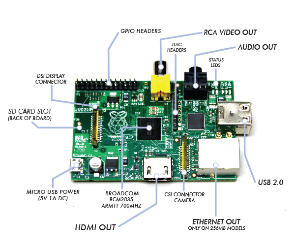
Of course, the “lead actor” on the RPi board is the Broadcom BCM2835, System on a Chip (SoC). Broadcom bills this chip as a “multimedia applications processor for advanced mobile and embedded applications that require the highest levels of multimedia performance”. Maybe more importantly for the DIY/Hacker community is that all the firmware running on the chip is now open source.
There is another big chip, that being the SMSC LAN9512/LAN9512i USB Hub & Ethernet Controller. This is the major work horse in getting data in/out of the RPi for USB peripheral devices and IP networking.
Now note that most of the board’s other large components are for data I/O. Specifically, the HDMI, RCA Video, and Audio Out (3.5mm jack) are output only (at least for general purpose data communication perspective), and therefore, not part of our discussion. On the other hand, the USB and Ethernet ports, are powerful and widely supported serial communication devices, but I will only lightly touch the USB. I want to focus on serial communication with simple/bare-bone devices, like an LCD 16×2 display, which generally are not interface via something as sophisticated at USB or Ethernet. But the USB can be used to some for some types of device interfacing, so I will cover that as a final topic.
There are three other board components that concern themselves with data communications but will not be covered in this post:
- JTAG Header: The JTAG Header is used as a debug port. Embedded systems developer relies on debuggers communicating with chips via the JTAG to perform operations like single stepping and break-pointing. In time, I suspect people will find ways to exploit these pins for both good & evil, but for now, this is for the RPi hardware development community to use.
- CSI Camera Connector: The Camera Serial Interface (CSI) specification is a standard interface between a camera and a host processor for mobile device applications. This will be where you’ll connect cameras and video devices to the RPi.
- DSI Display Connector: The Display Serial Interface (DSI) is a specification aimed at reducing the cost of display sub-systems in a mobile device. This is commonly targeted at LCD and similar display technologies. RPi may be able to interface to some of these. Some graphical LCD/OLED displays might be attached to it. DSI would seem like a good candidate for implementing my LCD display but there is a problem. It appears the DSI isn’t supported at this time.
This leaves one remaining board input/output component standing, that be the General Purpose Input/Output (GPIO). On some electronics boards, GPIO pins have no special purpose defined, and some pins go unused by default. The RPi developer has identified a handful of digital control lines and provided services on them for you to use. By having these available can save you the hassle of having to arrange additional circuitry to provide them or implement functionality in software.
Raspberry Pi’s GPIO as a Data Bus
The first thing to get your head around, is how is data moved around the RPi, or in any general purpose computer. In the most general sense in electronics, a bus or data bus is used to move data words of any type from one place to another. Computing is based on data words made up of collections of data bits. These “words” can contain as few as four data bits and often much larger.
The task of a bus designer is to devise circuitry that passes these data words from one circuit to another. These words can be communicated serially (i.e. serial communications) or in parallel.
- Serial Bus: The least expensive method in terms of wire cost is to send the bits one at a time over a single pair of wires. This is called serial data transmission. Data words start as sets of bits that exist in parallel. In order to ship these words on a serial basis they must be converted to a serial stream of bits at the transmit end and then reconverted to a parallel word at the receive end. The common name for the circuitry that does this conversion is a SerDes circuit which stands for serializer/deserializer. Integrated circuits are more expensive when they have more pins. To reduce the number of pins in a package, many ICs use a serial bus to transfer data when speed is not important. Some examples of such low-cost serial buses include Serial Peripheral Interface (SPI), Inter-Integrated Circuit (I²C), UNI/O, and 1-Wire.
- Parallel Bus: At some point, it is more cost effective to add a wire for each bit in the word and send it in parallel on a data bus. Parallel buses have a limited data rate and distance at which they can be reliably run (more so than a serial bus). Some widely used parallel bus standards are Parallel Bus Interface (PBI), Peripheral Component Interface (PCI), Small Computer Systems Interface (SCSI), the VMEbus used in instrumentation, the Rambus interface used in memories, and others.
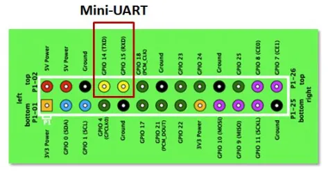
As the name implies, GPIO pins can be configured through software to provide some specific function or purpose within the hardware device design. The GPIO pins connect directly into the core of the processor, and the Raspberry Pi developers implemented several alternate functions for the GPIO pins. Several are desirable because of the multiple standards and types of devices you may wish to interface. On boot-up, the RPi board GPIO is in alternate function state “ALT0” and will support I2C, SPI, and UART. This is shown below:

It can be confusing to call the RPi’s whole 26 pin array GPIO and also some specific pins GPIO. In reality, all the GPIO pins can be reconfigured to provide alternate functions.
While PCM isn’t a topic for this posting, in the figure above, you’ll also see references to PCM on pins 18 & 21. PCM stands for Pulse-code modulation and is s a method used to digitally represent analog signals. It is often used to control light intensity or motors. RPi’s native PCM capabilities are not well documented but it appears that people have has some success. Generally, to do anything useful, you need multiple PCM channels so people have resorted to adding hardware or software to get the desired functionality from the RPi. My guess is these RPi pins don’t have much of a future.
I2C, SPI, UART … Say what?
Much has been lightly covered so far, including terms like I2C, SPI, and UART. So what is the significance? Well, I2C, SPI, and UART are the heart of our quest to understand RPi’s serial communications capability. Via their exposure on the GPIO pins, these capabilities are what can be used to integrate things like LCD displays to the RPi. Now lets dive deeper into each one of them.
Universal Asynchronous Receiver/Transmitter (UART)
The Universal Asynchronous Receiver/Transmitter (UART) takes bytes of data and transmits the individual bits in a sequential fashion. The device changes processor’s parallel information to serial data which can be sent on a communication line. A second UART (maybe on another processor) can be used to receive the serial information. The UART performs all the tasks, timing, parity checking, etc. needed for the communication. The only extra devices attached are line driver chips capable of transforming the TTL level signals (0/5 volts) to line voltages (on RS-232 line this could be as +/- 25 volts) and vice versa.
Each UART contains a shift register, which is the fundamental method of conversion between serial and parallel forms. Serial transmission of digital information (bits) through a single wire or other medium is much more cost effective than parallel transmission through multiple wires. The UARTs transmit/receive one bit at a time at a specified data rate (i.e. 9600bps, 115,200bps, etc.). This method of serial communication is sometimes referred to as TTL serial communications.
Asynchronous transmission allows data to be transmitted without the sender having to send a clock signal to the receiver. Instead, the sender and receiver must agree on timing parameters in advance and special bits are added to each word which are used to synchronize the sending and receiving units. When a word is given to the UART for Asynchronous transmissions, a bit called the “Start Bit” is added to the beginning of each word that is to be transmitted. The Start Bit is used to alert the receiver that a word of data is about to be sent, and to force the clock in the receiver into synchronization with the clock in the transmitter.
For a further description of synchronous and asynchronous line communications, check out this tutorial.
Raspberry Pi’s Mini-UART
Warning: Misleading information ahead – See Warren Gay’s comments.
The Raspberry Pi actually has two UARTs. One UART is part of the internal ARM architecture of the Broadcom BCM2835 chip, in the core of the Raspberry Pi and not accessible externally. The other UART is sometimes called the RPi’s “Serial Port” (even thou the USB supports serial communications, and therefore a serial port). The serial port being reference here is serviced by a UART, sometime refereed to as the “Mini-UART” since it doesn’t appear to be very rich in functionality. It is basically be used as a console port for access to the Raspberry Pi. The serial console is a convenient way to interact with the Raspberry Pi for debugging or your network is down and it is the destination of console messages (including boot-up messages). From the Raspberry Pi pinout and the eLinux wiki, I can see that the serial port (aka Mini-UART) on the Pi is on GPIO Pin 14 (TX) and GPIO Pin 15 (RX):
Since the GPIO pins give access to the Mini UART, you can establish a serial console, which can be used to log in to the Pi, and many other things. However, normal console device communicate with -12V (logical “1″) and +12V (logical “0″) RS-232, which may just fry something in the 3.3V Pi. Even “TTL level” serial at 5V runs the same risk. See this tutorial for one example on how to build 3.3V to RS-232 levels converter with a MAX3232CPE and a few passive components.
You can reconfigure the RPi so that the Mini UART isn’t acting as a serial console and use it for outer purposes (e.g. communicate with an attached Arduino or Xbee). Using the Raspberry Pi’s serial port requires some Linux reconfiguration and the abandonment of the serial console, and potentially some level conversion, but it could be useful. The Mini-UART pins to provide access to Linux’s /dev/ttyAMA0 serial port. To be able to use the serial port to connect and talk to other devices, the serial port console login needs to be disabled and the post “Raspberry Pi and the Serial Port” shows you how.
Again, keep in mind that RX and TX lines are available on the GPIOs but operate at 3.3 volts. You’ll need a board or cable to level convert 3.3 volt UART signals to connect with other devices (e.g. RS-232, USB).
Serial Peripheral Interface Bus (SPI) — aka 4-Wire Serial Bus
The Serial Peripheral Interface Bus or SPI (pronounced as either S-P-I or spy) bus is a synchronous serial data link standard, named by Motorola, that operates in full duplex mode. SPI is much simpler than I2C. Master and slave are linked by three data wires, usually called MISO, (Master in, Slave out), MOSI (Master out, Slave in), the SCLK clock line (sometimes called M-CLK), and an optional SS (Slave Select; sometimes known as the Chip Select or CS line or Chip Enable or CE line) is the slave select or chip select line. Its optional only if you have one slave, otherwise one or more SS lines are provided. The Raspberry Pi has two Slave Select lines: CE0 and CE1.

Usually the transfer sequence consist of driving the SS line low, sending X number of clock signals with the proper polarity and phase, then driving the SS line high to end the communication. As the clock signals are generated, data is transferred in both directions, therefore in a “transmit only” system the received bytes have to be discarded and in a “receive only” system a dummy byte has to be transmitted.
Many SPI-enabled ICs and Microcontrollers can cope with data rates of over 10MHz, so transfer is much faster than with I2C. Since it is synchronous communications, it is not limited to 8-bit words so you can send any message sizes with arbitrary content and purpose. The SPI interface does not require pull-up resistors, which translates to lower power consumption. The downside is that SPI normally has no addressing capability; instead, devices are selected by means of a SS signal which the master can use to enable one slave out of several connected to the SPI bus. If more than one slave exists, one chip select line is required per device, which can use precious GPIO lines on the Master.
Inter-Integrated Circuit (I2C) — aka 2-Wire Serial Bus
Inter-Integrated Circuit or I2C (pronounced as either I-squared-C or I-2-C) is generically referred to as a “two-wire interface”. It’s a multi-master serial single-ended computer bus invented by Philips that is used to attach low-speed peripherals to a motherboard, embedded system, cellphone, or other electronic device.
I2C can be used to connect up to 127 nodes via a bus has two data wires, called SCL and SDA. SCL is the clock line. It is used to synchronize all data transfers over the I2C bus. SDA is the data line. Of course, there is a third wire being ground. There may also be a 5 volt wire to distribute power to the devices. Both SCL and SDA lines are “open drain” drivers. What this means is that the chip can drive its output low, but it cannot drive it high. For the line to be able to go high you must provide pull-up resistors to the 5v supply. There should be a resistor from the SCL line to the 5v line and another from the SDA line to the 5v line. The value of the resistors is not critical. Anything from 1800 ohms to 47K ohms used (1.8K, 47K and 10K are common values). You only need one set of pull-up resistors for the whole I2C bus, not for each device, as illustrated below:

In theory the I2C bus can support multiple masters, but most micro-controllers can’t. A master is usually a microcontroller, although it doesn’t have to be. Slaves can be ICs or microcontrollers. When the master wishes to communicate with a slave it sends a series of pulses down the SDA and SCL lines. The data that is sent includes an address that identifies the slave with which the master needs to interact. Addresses take 7 bits out of a data byte; the remaining bit specifies whether the master wishes to read (get data from a slave) or write (send data to a slave).
Some devices have an address that is entirely fixed by the manufacturer; others can be configured to take one of a range of possible addresses. When a micro-controller is used as a slave it is normally possible to configure its address by software, and for that address to take on any of the 127 possible values. The address byte may be followed by one or more byes of data, which may go from master to slave or from slave to master.
When data is being sent on the SDA line, clock pulses are sent on the SCL line to keep master and slave synchronised. Since the data is sent one bit at a time, the data transfer rate is one eighth of the clock rate. The original standard specified a standard clock rate of 100KHz, and most I2C chips and micro-controllers can support this. Later updates to the standard introduced a fast speed of 400KHz and a high speed of 1.7 or 3.4 MHz. The Arduino and Raspberry Pi can support standard and fast speeds.
The fast rate corresponds to a data transfer rate of 50K bytes/sec which is too slow for some control applications. One option in that case is to use SPI instead of I2C.
1-Wire — aka 1-Wire Serial Bus
On a 1-Wire bus (sometime refered to as a “MicroLan”), a single master device communicates with one or more 1-Wire slave devices over a single data line, which can also be used to provide power to the slave devices. Devices drawing power from the 1-wire bus are said to be operating inparasitic power mode. When operating in parasite power mode, only two wires are required: one data wire, and ground. At the master, a 4.7k pull-up resistor must be connected to the 1-wire bus. With an external supply, three wires are required: the bus wire, ground, and power. The 4.7k pull-up resistor is still required on the bus wire.

Each 1-Wire device contains a unique 64-bit code, consisting of an 8-bit family code, a 48-bit serial number, and an 8-bit CRC. Before sending a command to a slave device, the master must first select that device using its code.
How do you use I2C, SPI, UART, or 1-Wire on the Raspberry Pi?
Now that we know the what & why for serial communications options on the Raspberry Pi, how do we use them? This topic deserves technical details and examples but this post has already run too long. I’m likely to do some specific implementation in the future, but for now I’ll reference some sources of information on the web.
First, lets be clear about the RPi software distribution I’m using, since not all will be supporting all these serial communications options. I’m using Adafruit’s Occidentalis distribution (based on “Wheezy”) which comes with hardware SPI, I2C, and 1-wire support. In the Occidentalis distribution, Adafruit has included in the Linux kernel the needed drivers. SPI and I2C has been implement on the GPIO pins as outline above. RPi doesn’t have a predetermined GPIO pin assignment for 1-Wire, but Adafruit choose GPIO pin 4 for 1-Wire. Note that this unassigned GPCLK0 (General Purpose Clock Voltage) function.
Given you have the Occidentalis distribution, you can check on the installation of I2C, SPI, and 1-Wire via the following:
- To validate I2C, connect any I2C device to power, ground, SDA and SCL. Then run
sudo i2cdetect -y 0to detect which addresses are on the bus.i2cdetectis a program to scan an I2C bus for devices. Also, you can list the I2C device drivers via the commandls /dev/*i2c*. This illustrates that RPi supports two I2C buses, 0 and 1. - To validate SPI, the command
ls /dev/*spi*will list two SPI devices, one each for the 0 & 1 SS lines. To go further, use the spidev_test.c tool described in Getting SPI working on the Raspberry Pi. - Occidentalis implementation of 1-Wire isn’t done via a kernel installed driver but bitbanged. Adafruit states that the implementation is “flakier than SPI or I2C” and they don’t have any tutorials. Maybe 1-Wire should be shelved for now.
There are some good RPi SPI & I2C tutorials on Adafruits. There are others on personal blogs but generally they are scares right now.
Attach Peripherals to the Raspberry Pi
Now that we know the in’s & out’s of serial communications with the RPi, what can be done to make the physical aspects of interfacing the board easier. Dealing with the GPIO pins on the board can be a pain. One solution is the Pi Cobbler which plug the GPIO pins into a solderless breadboard via a ribbon cable. My personal favorite is the Pi Crust. In this case, the confusing layout of GPIO pins are much more clearly organized and supplied with more useful female headers. A whole development environment will be supplied via PiFace Digital and Gertboard … when they become available.
The USB Serial Ports
As promised, the final topic is the USB port. The USB can be used for some types of device interfacing, particularly if you make it look like a simple serial port to the device. The conventional serial port (not the newer USB port) is a very old I/O (Input/Output) port. It’s slow compared to newer Universal Serial Bus (USB) serial devices, but conventional serial ports are still in use and many devices you’ll hook to your RPi will want to use them. Until around 2006, most new desktop PC’s had one but has been largely replaced by the USB. Conventional serial ports are still widely used in embedded systems, but the RPi choose to use the USB. Never the less, it is possible to put a conventional serial port device on the USB bus by using a Serial to USB Adapter hardware or cables. This could be necessary for some of the hardware hacking you’ll do with an RPi. (For example, I’ll be posting a project where I’ll use the RPi’s USB to talk to a XBee radio.)
USB does synchronous communications (synchronous means that bytes are sent out at a constant rate one after another in step with a clock signal tick) and transmits in special packets like a network. Conventional serial ports are typically asynchronous (i.e. “not synchronous”). Just like a network, USB can have several devices physically attached to it, including serial ports. Each device on it gets a time-slice of exclusive use for a short time. A device can also be guaranteed the use of the bus at fixed intervals. One device can monopolize it if no other device wants to use it.
Under Linux, each and every hardware device, including USB ports, are treated as a file and call a device file. A device file allows a user to access hardware devices, but shields the users from the technical details about the hardware. (This is unlike what we’ll see for the RPi GPIO interfaces where hardware level technical details must be address directly.) Under Linux, a conventional serial port will typically have a device file such as /dev/ttyS0, /dev/ttyS1, etc. but the USB serial ports will appear as /dev/ttyUSB0, /dev/ttyUSB1, etc. When your device is plugged in, Linux assigns the filename as it sees fit and isn’t always predicable (it doesn’t have to be this way). If you need to know what device file your serial device is connected too (and your software often needs to know), using a combination of the commands lsusb, dmesg, and grep, plus some basic insight, will often do the trick.
The lsusb command can show you the hubs connected to your system, but you won’t necessarily see any entries in /dev until you plug something into it, and what that entry may be will be dependent upon the type of device you are plugging in. The system doesn’t recognize new USB devices right away. It can take from a couple of seconds to as much as a minute. If I plug my Serial to USB Adapter cable, using the lsusb command I can identify the cables . Now using dmesg, and grepping for the “Manufacturer”, I can get the “FTDI”. Now I grep again for “FTDI” to get the device file name “ttyUSB0“. This is all illustrated below:


Thank you for the detailed analysis of all the things I don’t understand about the Pi! 😀
I believe your remarks about the mini UART are incorrect. If you look carefully at the Broadcom BCM2835 ARM Peripherals manual, in chapter 2 “Auxiliaries: UART1 & SPI1, SPI2” you’ll see that the mini UART is in fact UART1 (not UART0). Then if you check section 6.2 “Alternative Function Assignments”, you will see that it is TXD1 and RXD1 on GPIO 14 and 15 respectively, for ALT function 5, which is also NOT the default for the Pi.
When Raspbian linux boots up, it is in ALT function 0 for GPIOs 14 and 15, so this is accessing UART0, which is the good one that you say is “inaccessible”. 🙂 This is the one that is actually being supported by the driver /dev/ttyAMA0. Looking the driver source in driver/tty/serial/amba-pl011.c also strongly suggests that it is driving the PL011 device, not the mini.
FYI: According to the Broadcom documentation, you can get the RTS0 signal on GPIO 17 (P1-11) if you set it to ALT function 3. Likewise, the CTS0 is available on GPIO 30 (P5-05), if it is set to ALT function 3.
Warren —
You have clearly dived deeper into the murky waters of the Raspberry Pi than I, so I’m willing to bet your right. While writing this, I stumbled into documentation on the multiple UARTs and assumed the authors had their facts right.
Assuming …. always a bad idea. Thanks for the catch.
One of the joys of writing books is in the checking of facts. 🙂
Warren.
[…] Raspberry Pi Serial Communication: What, Why, and a Touch of How December 5, 2012 […]
Brilliant article, well done…
You actually make it seem really easy along with your presentation but I in finding
this matter to be actually something that I think I would never understand.
It sort of feels too complex and extremely
extensive for me. I am having a look forward for your next submit, I will try
to get the hold of it!
When using the bcm2835 i2c tools to talk with several slaves, do you have to use bcm_i2c_setSlaveAddress() each time you change the slave you which to write to, or read from? Also should bcm2835_i2c_begin(), and bcm_i2c_end() be used to bracket each set of messages?
I’m not familiar with the API that you’re citing here, with respect to function name “bcm_i2c_setSlaveAddress()”. When programming in C/C++, you would always set your address in struct i2c_msg, member addr (Chapter 14 of “Mastering the Raspberry Pi” ISBN: 978-1-4842-0182-4). But you must be using something else.
If you point to the actual software you are using, then someone can give you a more informed answer.
A serial port is a sequential statement physical interface throughout which detail transfers inside or outside one bit at a time. Data transfers via serial/sequential ports linked the computer to devices like workstation or modems.
http://www.whatisnetworks.com/router-serial-vs-ethernet/
tanx alot
I want to know about the communication protocols of raspberry pi camera
We are going to change the microprocessor of the board
[…] Linux. YOU DON’T NEED ANY OF THAT. With Wheezy on Pi, IJW.) Thanks to Jeff Skinner for his really useful blogpost, where I found this step and the next. In a terminal, […]